Point Grey Research Grasshopper Technical Reference
Camera Operations and Features
Revised 26-Nov-10
Copyright (c) 2010 Point Grey Research Inc.
40
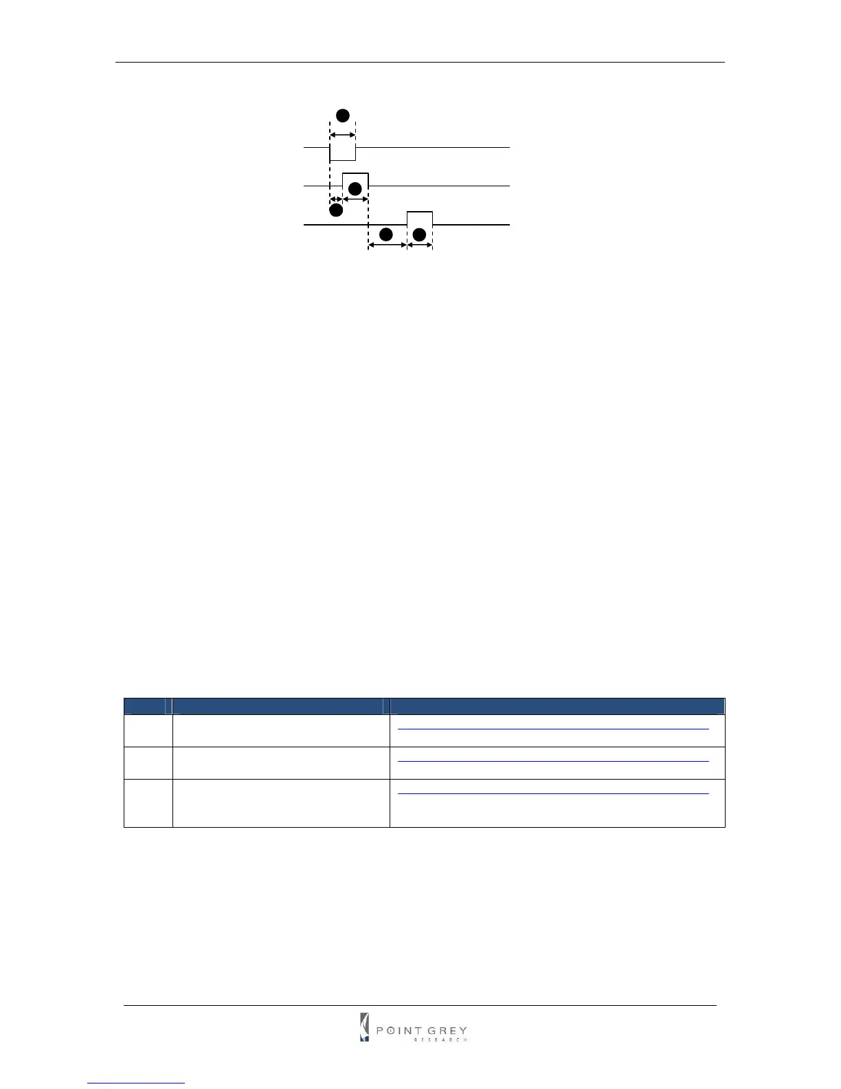
Figure 4: Grasshopper external trigger timing characteristics
It is possible for users to measure this themselves by configuring one of the camera’s GPIO pins
to output a strobe pulse (see the Programmable Strobe Output section) and connecting an
oscilliscope up to the input trigger pin and the output strobe pin. The camera will strobe each time
an image acquisition is triggered; the start of the strobe pulse represents the start of exposure.
4.5.10.2. Ensuring Trigger is Armed
It is possible for the Grasshopper to be in asynchronous trigger mode but not be ready to accept
a trigger. The reason for this is that the camera may be currently exposing an image; the camera
is only ready to be triggered again when this image finishes integrating and is completely read off
of the CCD.
To ensure that the camera is ready to be triggered, poll the SOFTWARE_TRIGGER register
0x62C or SOFT_ASYNC_TRIGGER register 0x102C. The concept of polling to ensure the trigger
is armed is demonstrated in the AsyncTriggerEx example program distributed with the FlyCapture
SDK.
Once the trigger is reporting that it is armed, there should be no delay between when the user
can enable isochronous transmission and when they can trigger the camera. In fact, it is possible
to trigger the camera before iso is enabled and receive the image that was triggered, provided iso
is enabled at some point during exposure. For example, assuming a 10ms shutter
time, it is possible to trigger the camera, enable iso 5ms after, and still receive the triggered
image.
Related Knowledge Base Articles
ID Title URL
169 Time between software trigger
and start of integration.
www.ptgrey.com/support/kb/index.asp?a=4&q=169
177 Maximum frame rate possible in
external trigger mode_0.
www.ptgrey.com/support/kb/index.asp?a=4&q=177
221 Synchronizing to an external
signal using DCAM 1.31
Trigger_Mode_0
www.ptgrey.com/support/kb/index.asp?a=4&q=221
4.5.10.3. Minimum Trigger Pulse Length
The minimum trigger pulse length than the camera will respond to is 16 ticks of the current pixel
clock. The pixel clock frequency can be read from the floating point PIXEL_CLOCK_FREQ
register 0x1AF0.
1
2
3
4 5
External trigger
Exposure time
Data transfer
n min 1μs
o less than 10μs
p shutter time
q 1ms
r 30ms (30 FPS)