Point Grey Research Grasshopper Technical Reference
Camera Operations and Features
Revised 26-Nov-10
Copyright (c) 2010 Point Grey Research Inc.
46
4.6.8. Embedded Image Information
The Grasshopper has a feature that allows image timing and camera settings information to be
embedded in the first several pixels of each image. This feature is controlled using the
FRAME_INFO register 0x12F8, which is described in detail in the PGR IEEE-1394 Digital
Camera Register Reference.
4.7. Camera and Device Control
4.7.1. Voltage Sensor
The Grasshopper has an on-board sensor that allows the user to monitor a variety of different
voltages, including the current 1394 bus voltage. This feature can be accessed using the
VOLTAGE registers 0x1A50 – 0x1A54, which are described in detail in the PGR IEEE-1394
Digital Camera Register Reference.
4.7.2. Programmable Strobe Output
The Grasshopper is capable of outputting a strobe pulse off one or all of its GPIO pins. By
default, a pin that is configured to be a strobe output will output a pulse each time the camera
begins integration of an image. Setting a strobe duration value of zero will produce a strobe pulse
indicating the exposure (shutter) time.
The Grasshopper can also be configured to output a variable strobe pulse pattern. The strobe
pattern functionality allows users to define the frames for which the camera will output a strobe.
For example, this is useful in situations where a strobe should only fire:
• Every Nth frame (e.g. odd frames from one camera and even frames from another); or
• N frames in a row out of T (e.g. the last 3 frames in a set of 6); or
• Specific frames within a defined period (e.g. frames 1, 5 and 7 in a set of 8)
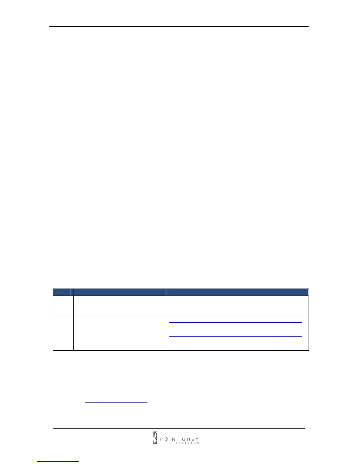
Related Knowledge Base Articles
ID Title URL
179 Setting a GPIO pin to output a
signal using DCAM v1.31 strobe
functionality
www.ptgrey.com/support/kb/index.asp?a=4&q=179
207 Setting a GPIO pin to output a
strobe signal pulse pattern
www.ptgrey.com/support/kb/index.asp?a=4&q=207
212 GPIO strobe signal continues
after isochronous image transfer
stops
www.ptgrey.com/support/kb/index.asp?a=4&q=212
4.7.3. RS-232 Serial Port
The Grasshopper is capable of serial communications at baud rates up to 115.2Kbps via the on-
board logic level serial port built into the camera’s GPIO connector. To use this functionality, a
level converter must be used to convert the TTL digital logic levels to RS-232 voltage levels. B&B
Electronics (
http://www.bb-elec.com/) part number 232LPTTL can be used for this conversion.