BODY / STEERING / SUSPENSION
5.10
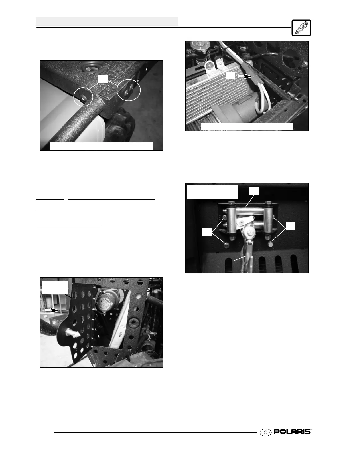
5. Remove the T--27 screws (C) that secure the side
tube supports to the rear rack (each side).
C
Reassembly: 14--16 ft.lbs. (19--22 Nm)
6. Remove the rear rack and brushguard assembly.
7. For reassembly of the rear brushguard and rack
reverse the removal procedure. Refer to the
torque specifications provided.
WARN® WINCH REMOVAL /
INSTALLA
TION
FRONT WARN® WINCH
1. Disconnect the negative battery cable from the
battery.
2. Disconnect wires from the Warn® winch or
disconnect the quick connect harness (A) located
above the radiator. Access can be gained to the
cables through the left front access door.
Access
Door
Top View with Top Rack Removed
A
3. Remove the hook from the winch cable.
4. Remove the four bolts (B) that secure the winch to
the front mounting area. Remove the fairlead (C)
if necessary to gain access to the top bolts.
C
B
B
Reassembly:
18 ft.lbs. (24 Nm)
Hook
5. For installation reverse the steps for removal.
 Loading...