3.80
9924880 Rev 2- 1/10/2014 - 2013 / 2014 RANGER XP 900 - 2014 RANGER XP 900 / CREW 900 Service Manual
© Copyright Polaris Sales Inc.
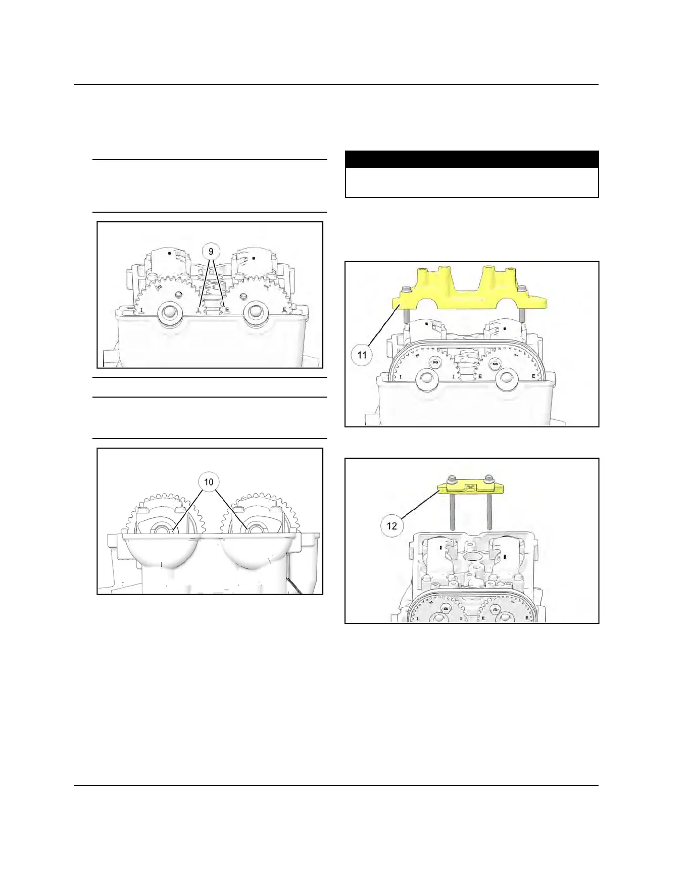
13. Verify cam timing is correct. Flywheel TDC mark
should still be aligned (see Step 1) and cam sprocket
markings should line up as shown.
Timing View for Sprockets
For correct sprocket orientation, ensure the “I” for
intake on cam 1204052 and the “E” for exhaust on
cam 1204053 are positioned as shown
o
. View
from mag side.
Timing View for Camshafts
Align slot of both cams with the top deck of the
head
a
. Position 4mm thick flat bar through slots
to lock cams in correct position.
14. If timing marks are not aligned, remove sprockets
and correct alignment.
15. Remove the Cylinder Holding & Camshaft Timing
Plate (PU-50563) from the end of the camshafts.
16. Apply Polaris PS-4 engine oil to the cam chain
tensioner bore prior to assembly.
17. Rotate the engine using the flywheel and install the
remaining bolt in each camshaft sprocket. Hold
camshafts in place with an open-end wrench and
torque the sprocket bolts to specification.
TORQUE
Camshaft Sprocket Bolts:
11 ft-lb (15 Nm)
18. Rotate the engine using the flywheel and torque the
remaining sprocket bolts to specification.
19. Install the front camshaft carrier
s
and two outer
retaining bolts.
20. Install the fixed cam chain guide
d
and two retaining
bolts.
ENGINE
 Loading...