ZONEMASTER ZONETOUCH V2 ZONE CONTROL SYSTEM - Installation Manual
7
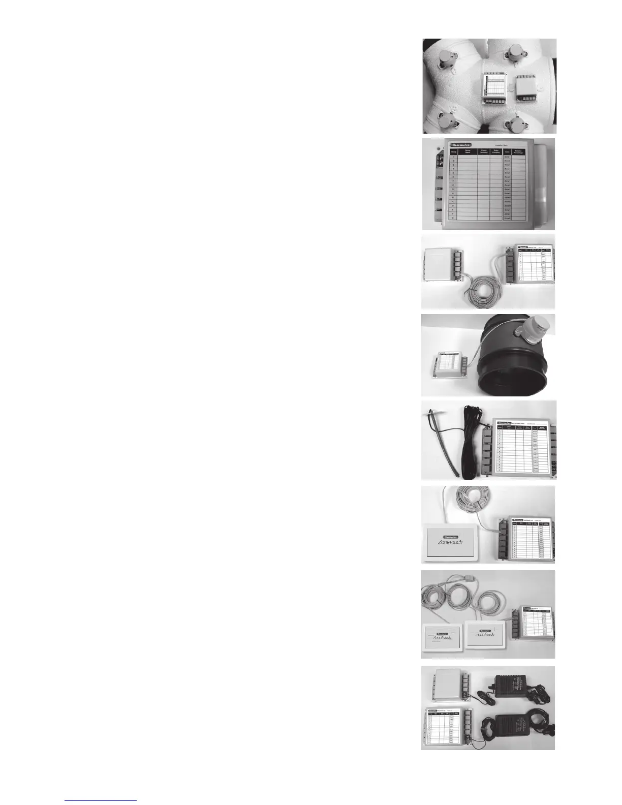
6) Component Installation
6.1 Mountthemaincontrolmoduleand/orextension
module(ifusingmorethan8zones)byscrewing
thebox(es)toaroofframeorPolyaireDiusion
Fitting(PDF).
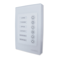
6.2 Remove thetwo-sidecoversonthemaincontrol
modulesothatallLEDsandsocketsforzone
dampersareexposed.
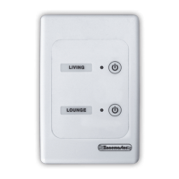
6.3 If extensionmoduleisused,connectmainmodule
toextensionmoduleat‘E’portonbothmodules
withaonemetreleftlatchedcable(provided).
6.4 Use pre-testedcabletoconnect‘Z1’portonthe
mainmoduletothemotorizeddamperofthe1st
zone.
6.5 Repeat step6.4toconnectotherzonedampers,
includingbypassdamper(‘B’port)ifinstalled,
totheirrelevantzoneportsonthemaincontrol
moduleandextensionmodule.
6.6 Mount the supply air sensor in the supply air duct
betweenthefancoilandtherstdamperandpush
the plug of supply air temperature sensor into the
socketonthemaincontrolmodule(Optional).
6.7 Connectthetouchscreentothe‘T’portonthe
mainmodule.Iftwotouchscreensareused,
usetheprovidedleftlatchedcablesanda1-to-2
female-femalesplittercouplertojoinalltouch
screens.(Seeinstructionsbelowontmentof
touch screen to wall).
6.8 Connect the 24VAC transformer to screw terminals
onthemaincontrolmodule.Ifextensionmoduleis
used,connectanother24VACtransformertothe
screwterminalsoftheextensionmodule.