Design Guide for the Polycom SoundStructure C16, C12, C8, and SR12
7 - 4
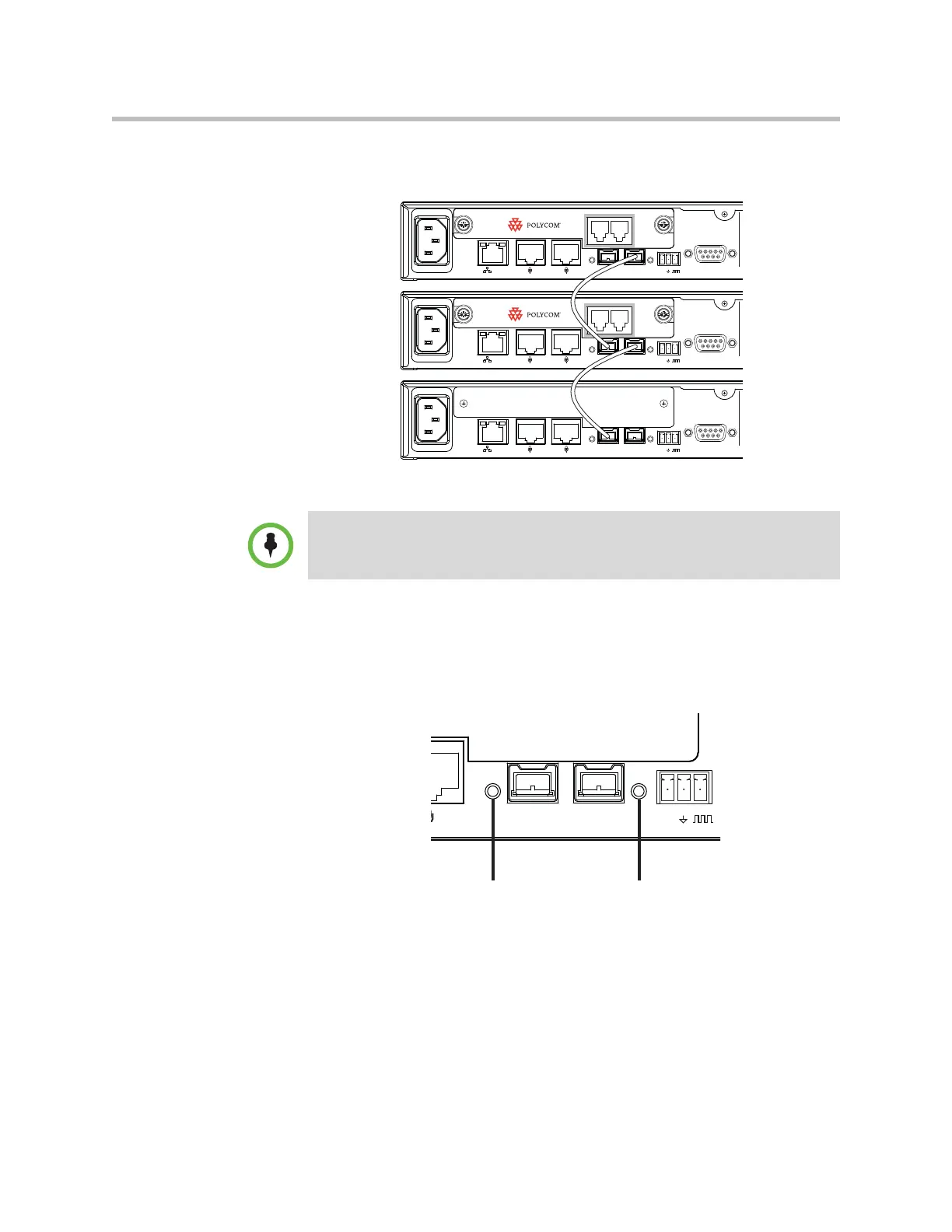
If two telephony cards are required, install the second telephony card in the
second SoundStructure device as shown in the following figure.
Rear Panel OBAM LED Status
Once the devices are linked together, apply power to the SoundStructure
devices. Once the SoundStructure devices have finished booting, the OBAM
status LED’s, shown in the following figure, will indicate the status of the
OBAM link.
PIN 2: TXD
PIN 3: RXD
PIN 5: GROUND
PIN 7: CTS
PIN 8: RTS
LAN
C-LINK2
OBAM IR
RS-232
IN OUT
12V
PHONE LINE
PIN 2: TXD
PIN 3: RXD
PIN 5: GROUND
PIN 7: CTS
PIN 8: RTS
LAN
C-LINK2
OBAM IR
RS-232
IN OUT
12V
PHONE LINE
PIN 2: TXD
PIN 3: RXD
PIN 5: GROUND
PIN 7: CTS
PIN 8: RTS
LAN
C-LINK2
OBAM IR
RS-232
IN OUT
12V
Telephony cards should be inserted into devices starting with the master device
and working down the OBAM link (increasing bus IDs) if more than one telephony
card is required.
OBAM In
Status LED
OBAM Out
Status LED