3300 ACM Installation and Operation Manual Power Measurement Ltd.
Installation 2-9
MODEL: 3300 ACM
SERIAL NUMBER:
OPTIONS:
ELECTRICAL RATINGS
POWER
MEASUREMENT
LTD.
6703 RAJPU
VICTORIA, B.
CANADA V8
MADE IN
CANADA
+
-
I32
I31
I22
I21
I12
I11
V3
V2
V1
L
N
G
2A
2A
OPTIONAL PT POLARITY CONNECTION
V
AB
CT SHORTING SWITCH
OR TEST BLOCK
SWITCHGEAR CHASSIS
GROUND
2A
2A
V
CB
LOAD
EXPORT/REVERSE/NEGATIVE
IMPORT/FORWARD/POSITIVE
ABC
SWITCHGEAR CHASSIS
GROUND
LINE
Base Module
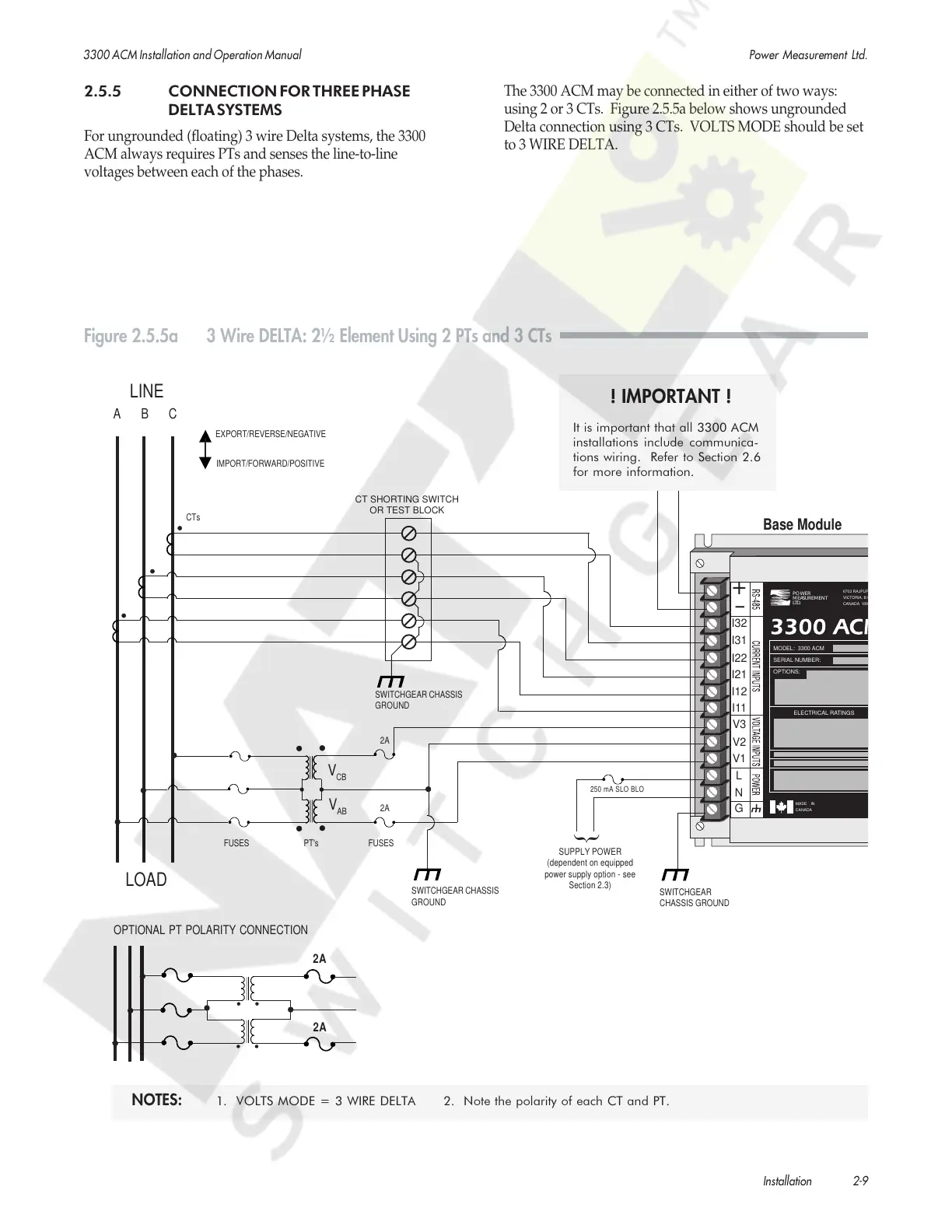
Figure 2.5.5a 3 Wire DELTA: 2½ Element Using 2 PTs and 3 CTs
CTs
SWITCHGEAR
CHASSIS GROUND
SUPPLY POWER
(dependent on equipped
power supply option - see
Section 2.3)
{
250 mA SLO BLO
FUSES PT's FUSES
! IMPORTANT !
It is important that all 3300 ACM
installations include communica-
tions wiring. Refer to Section 2.6
for more information.
2.5.5 CONNECTION FOR THREE PHASE
DELTA SYSTEMS
For ungrounded (floating) 3 wire Delta systems, the 3300
ACM always requires PTs and senses the line-to-line
voltages between each of the phases.
The 3300 ACM may be connected in either of two ways:
using 2 or 3 CTs. Figure 2.5.5a below shows ungrounded
Delta connection using 3 CTs. VOLTS MODE should be set
to 3 WIRE DELTA.
NOTES: 1. VOLTS MODE = 3 WIRE DELTA 2. Note the polarity of each CT and PT.
Courtesy of NationalSwitchgear.com
 Loading...