- 23 -
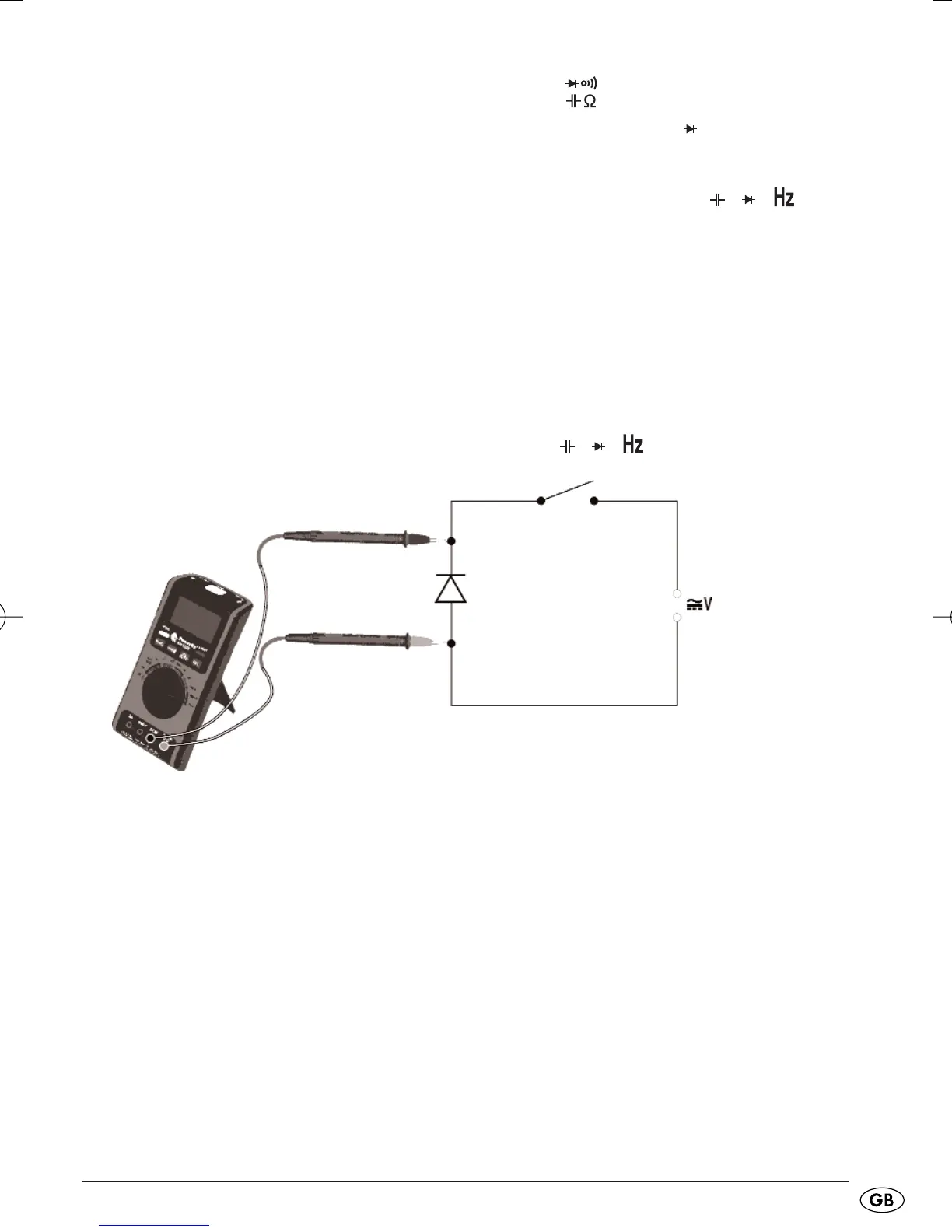
• Place the function switch
q
at the position .
• Press the button
FUNC.
r
repeatedly until the indicator for diode
measurement appears in the display
z
.
• Insert the measuring leads into the input sockets
VΩ
7
and COM
8
.
• Connect the measurement prods with the object being tested. Thereby,
connect the red measuring lead with the anode (+) and the black mea-
suring lead with the cathode (-).
The conducting state voltage drop in volts (V) can now be read off from
the display
z
.
The polarity of the test voltage on the socket
VΩ
7
is positive "+".
Typical values:
Schottky- or Germanium diodes: approx. 0,2...0,4 V
Silicon: approx. 0,6...0,8 V.
Cathode/Anode
In general, the cathode is the minus pole, that is, the electrode that takes up
the electrons over the electrical connection and passes them on in the direction
of the anode (+).