Chapter 5 Function parameter
62
DIx
DIn
DIy
COM
Forward run FWD
Three-wire operation
control
Digital common
terminals
Reverse run REV
SB2
SB1
SB3
Figure 5-5:Terminal command mode:Two-wire mode 1
Of which: SB1: Stop button SB2: Forward button SB3: Reverse button
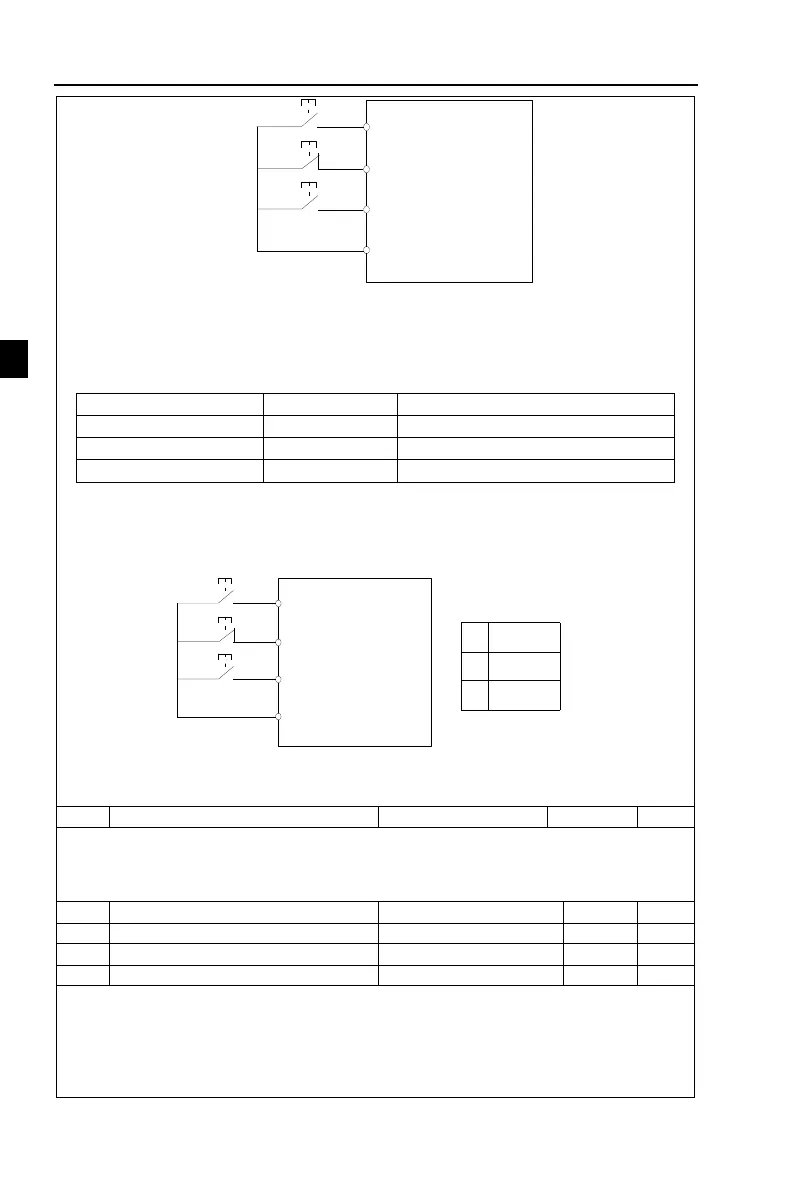
3:Three-wire control mode 2
In the mode, DIn is the enabled terminal, the running commands are given by DIx, the
direction is determined by the state of DIy.
The terminal function is set as follows:
Three-wire operation control
To run, firstly close DIn terminal, the motor run signal is generated by the ascendant edge
of DIx, the motor direction signal is generated by DIy status.
To stop, you must disconnect DIn terminal signals Of which, DIx, DIy and DIn are the
multi-function input terminals of DI1 to DI10, DIx is for active pulse, DIy and DIn are for
active level.
DIx
DIn
DIy
COM
Forward run FWD
Three-wire operation
control
Digital common
terminals
Reverse run REV
SB2
SB1
K
K
Running direction
0
1
Forward
Reverse
Figure 5-6:Terminal command mode:Three-wire mode 2
Of which:
SB1: Stop button SB2: Run button
Terminal UP / DOWN change rate
Used to set terminal UP/DOWN adjustment frequency, the rate of frequency change, i.e.
frequency change amount per second.
When F0.02 (Frequency decimal point) is 2, the value range is 0.001Hz/s to 65.535Hz/s.
When F0.22 (Frequency decimal point) is 1, the value range is 0.01Hz/s to 655.35Hz/s.
Minimum input value for AI curve 1
Minimum input setting for F1.12
Maximum input value for AI curve 1
F1.14 corresponding setting
The above function codes are used to set the relationship between analog input voltage and
its representatives set value.
When the analog input voltage is more than the set Maximum Input (F1.14), the analog
voltage takes the Maximum Input as the calculated value, Similarly, when the analog input
voltage is less than the set Minimum Input (F1.12), according to the Setting Selection For AI
Less Than Minimum Input (F1.25), the analog voltage takes Minimal Input or 0.0% as the
 Loading...

