Chapter 5 Function parameter
92
Triangle wave rise time coefficient
Wobbulate cycle: The time of a complete wobbulate cycle.
Triangle wave rise time coefficient(E0.04), the time percentage of Riangle Wave Rise
Time relative to Wobbulate Cycle(E0.03) Triangle wave rise time = Wobbulate cycle(E0.03) ×
Triangle wave rise time coefficient(E0.04), unit: Second(S). Triangle wave drop time =
Wobbulate cycle(E0.03) × (1 - Triangle wave rise time coefficient(E0.04)), unit: Second(S).
The above function codes are used to fixed-length control.
The length information is sampled through the multi-function digital input terminal, the
pulse number sampled by terminal divides the pulse per meter(E0.07), so then the Actual
length(E0.06) can be computed out. When the Actual length is greater than the set length
(E0.05), the multi-functional digital DO will output "Length Arrival" ON signal.
During the fixed-length control, the multifunction DI terminal can be used to reset length
(DI function selects 28), please refer to F1.00 to F1.09 for details.
In some applications, the related input terminal function shall be set to "Length Count
Input"(Function 27), when the pulse frequency is higher, DI5 port must be used .
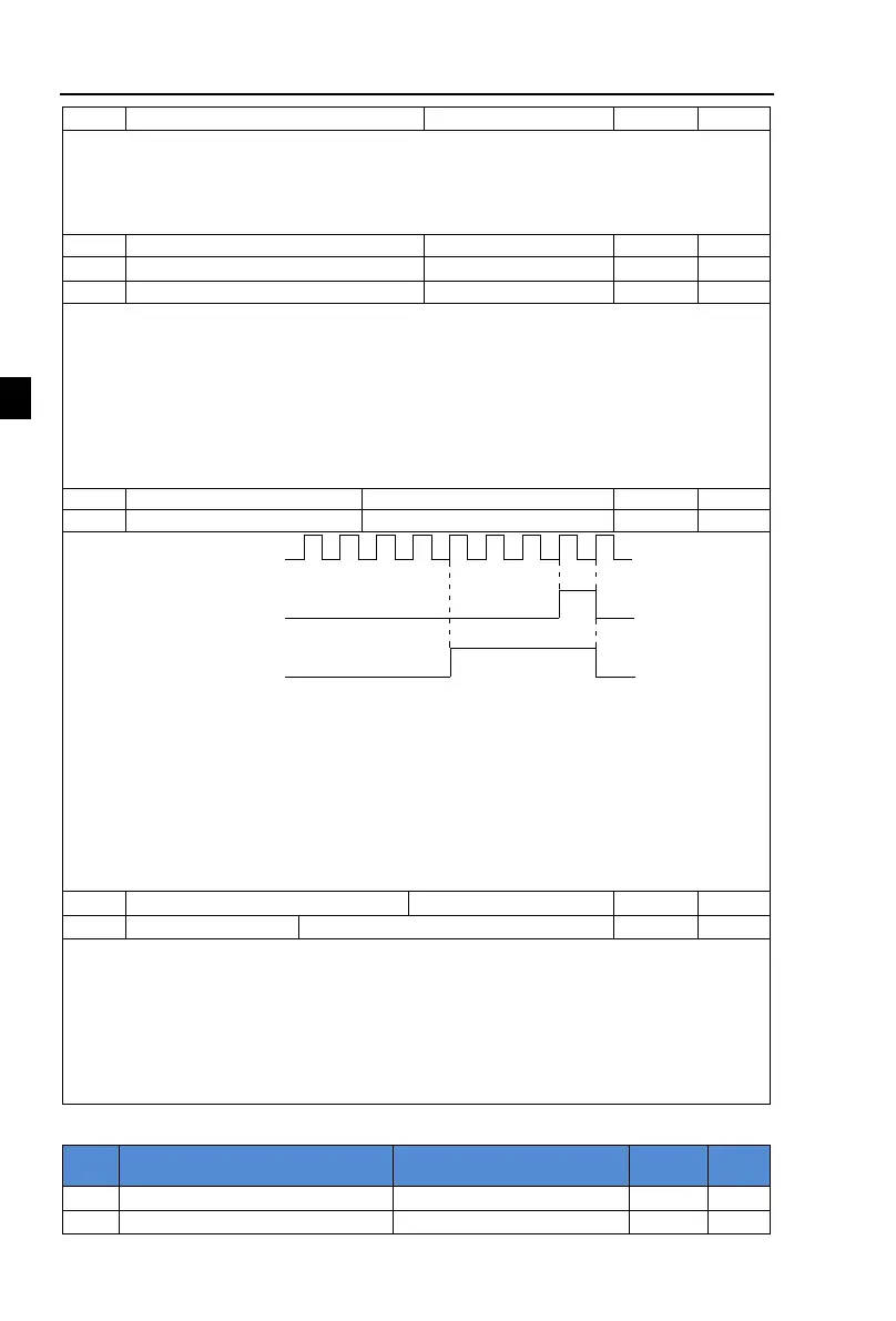
Set count value DO1
1
Count pulse DI5
Specified continue relay
2
3
4 5
6
7 8 9
Figure 5-29:Schematic diagram of the set count value reference and the snecified count value
The count value needs to be sampled through the multi-function digital input terminal. In
some applications, the related input terminal function shall be set to "Counter Input"(Function
25), when the pulse frequency is higher, DI5 port must be used .
When the count value reaches the set count value(E0.08), the multifunction digital DO will
output "Set Count Value Arrival" ON signal, then the counter stops counting.
When the count value reaches the specified count value(E0.09), the multifunction digital
DO will output "Specified Count Value Arrival" ON signal, then the counter continues to count,
and then stop till the set count value.
The figure is the schematic diagram of E0.08 = 8 and E0.09 = 4.
Reduction frequency pulse number
0.00Hz~F0.19(Max frequency)
Applications need to the corresponding input terminals function is set to "counter
input"(Function 25), when set count (E0.08) = count (d0.12) + reduction frequency pulse
number (E0.10), the converter automatically slow down to the set reduction frequency (E0.11)
run.
Remark: To reset the Count value need to the corresponding input terminals function be set
to "counter reset" (Function 26).
When count value (d0.12) is above reduction frequency pulse number, the converter can
not run.
5-2-16.E1 group Multi-stage command, simple PLC
 Loading...

