COMMERCIAL
PRO
D U C T S
DIVISION
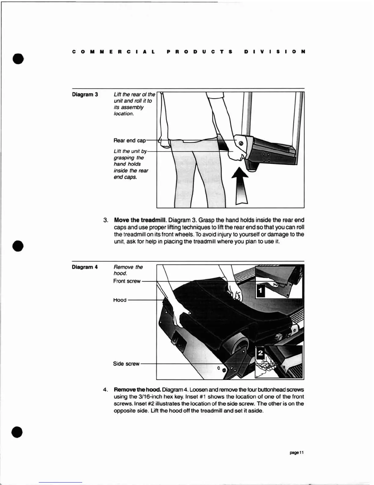
Diagram 3
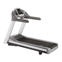
Diagram 4
Lift the rear
of
the
unit
and
roll it to
its assembly
location.
Rear end
cap-"itt-tr--"'l:::==;;;;t"
.....9
Lift the unit
by'--f--+--""T""----r==r
grasping the
hand holds
inside the rear
end caps.
3.
Move
the
treadmill. Diagram
3.
Grasp the hand holds inside the rear end
caps and use proper lifting techniques
to
lift the rear end
so
that you can roll
the treadmill on its front wheels.
To
avoid injury to yourself
or
damage to the
unit, ask for help in placing the treadmill where you plan to use it.
Remove the
hood.
Front screw
--~-\---:
Hood----+_
Side screw
--+--------:l\o-----
4. Removethe hood. Diagram
4.
Loosen
and
remove
the four buttonhead
screws
using the 3116-inch hex
key.
Inset
#1
shows the location
of
one
of
the front
screws. Inset #2 illustrates the location
of
the side screw. The other is on the
opposite side. Lift the hood off the treadmill and set it aside.
page
11