© Precor Incorporated, Unauthorized Reproduction and Distribution Prohibited by Law Page 113
Cable Connections
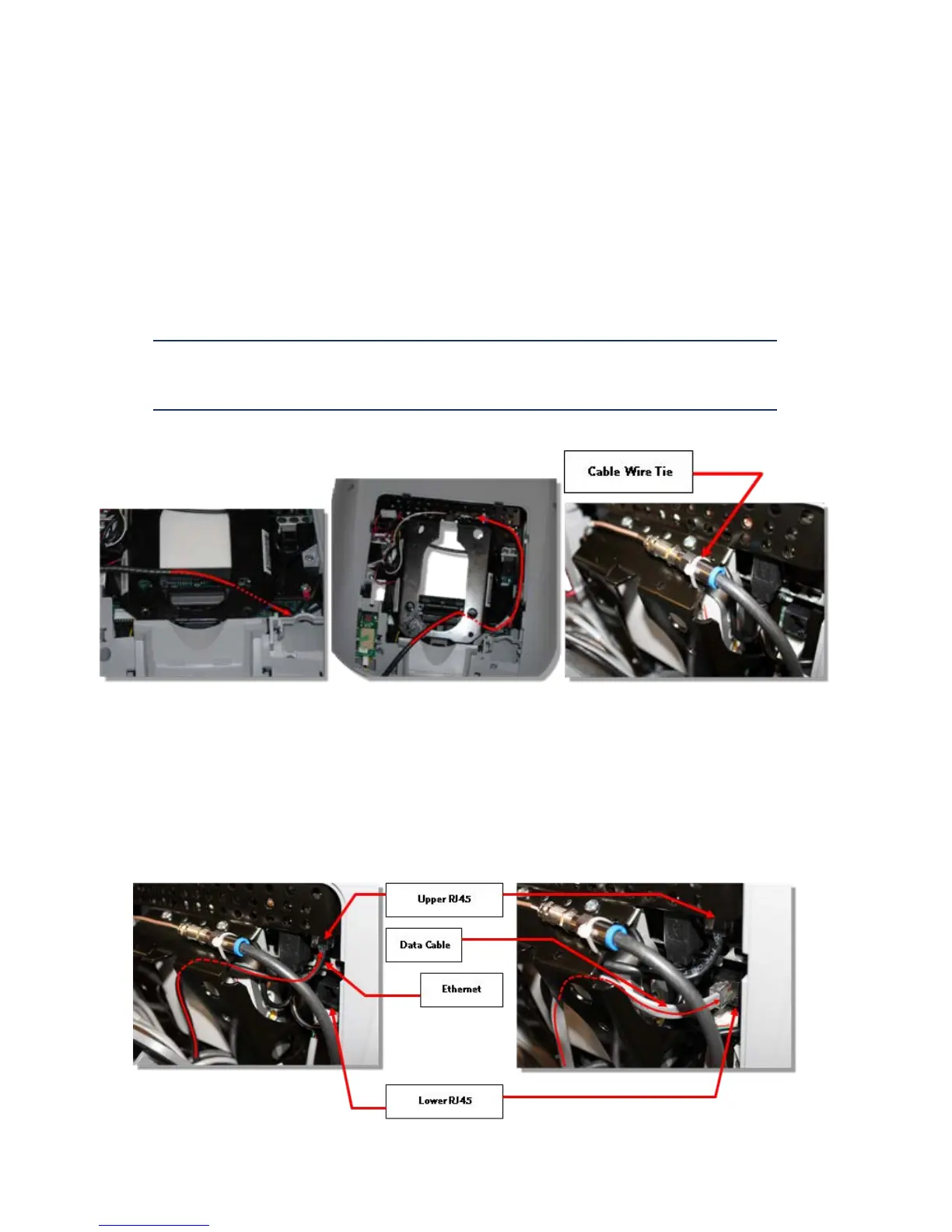
1 Route the RF coax cable down below the tuner and out the right bottom side of the armor. This is
easier if you straighten the cable and gently push it in the direction as shown in diagram below. Feed
about 10 inches of cable out though the plastic using your finger as a guide.
2 Bring the coax cable up over the top of the armor and connect it to the flexible cable attached to the
tuner.
3 Secure the RF coax connectors in place with a zip tie.
Note: It is important that the connection be tied to the frame in this location to
prevent the cable from being pinched, and the possibility of rattling noises during
use. Be sure to secure the zip tie on the connector and not on the cable.
4 Route the black, round Ethernet cable through the opening in the upper right side of the armor, behind
the tuner and connect the Ethernet cable to the upper RJ45 type connector.
5 Route the grey, flat Data cable through the opening in the upper right side of the armor, behind the
tuner and connect the Data cable to the lower RJ45 type connector.
Figure 73: Cable Connections