© Precor Incorporated, Unauthorized Reproduction and Distribution Prohibited by Law Page 10
1-Stop Switch Cable Routing
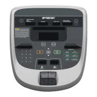
The Stop Switch assembly cable (treadmill only) should be routed through the lower right corner of the
armor, and connected to the 6 pin flat connector on the CPA board. The cable will go through the center
of the armor, out the bottom right side opening, then up to the connector. Be sure to get the connector
onto the six pins correctly or the treadmill will not work.
Figure 3: Stop Cable Routing (Treadmill Only)