21
Revision 01/2019 EN
PowerLossMonitor PLM
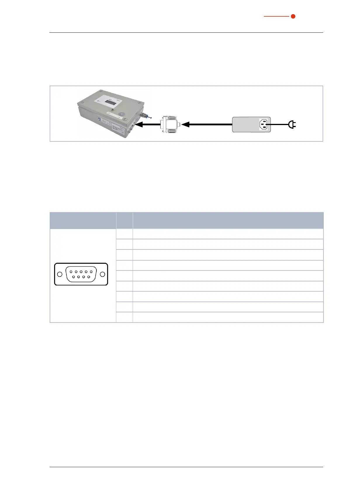
8.5 Connect the power supply
In order to operate, the PowerLossMonitor PLM requires a supply voltage of 24V±5%(DC). A suitable
power supply with an adapter unit is included in the scope of delivery. Please use only the provided connec-
tion lines.
PLM
PRIMES power supply
Adapter
Fig. 8.7: Connecting the power supply
Connect the power supply unit via the adapter with one of the 9pin D-Sub sockets (RS485) of the Power-
LossMonitor PLM.
8.6 PIRMES bus
The device is supplied with power by means of the 9 pin D-Sub sockets. Using a converter, the socket can
also be used to connect a PC to enable communication (see chapter 8.8 on page22).
D-Sub socket, 9 pin
(top view, plug-in side)
Pin Function
15
6
9
1 Ground
2 RS485 (+)
3
+24
V
4 Not assigned
5 Not assigned
6 Ground
7 RS485 (–)
8 +24V
9 Not assigned
Tab. 8.2: Pin assignment PRIMES bus
8.7 Connect the external temperature sensor
The temperature sensor is a Pt100 with a four-wire connection. Plug the connector cable into the corre-
sponding socket of the PowerLossMonitor PLM. The connection cable may have a length of up to 10m.
 Loading...