10
Revision 01/2019 EN
PowerLossMonitor PLM
4 Introduction
4.1 System description
The PowerLossMonitor PLM is a system that determines power losses especially in water-cooled compo-
nents of beam guidance systems.
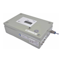
PLM 40
Red LED „Error“
Water flow rate is too low
Red LED „Error“
Water flow rate is too low
Display
Display
PLM 2/10/20
Fig. 4.1: Components of the PowerLossMonitor PLM
4.2 Measuring principle
The PowerLossMonitor PLM measures the water flow rate of the cooling water as well as the temperature
difference between inflowing and outflowing water. These values are then used to calculate the power induct-
ed in the cooling water.
If the mounting of the beam deflection mirrors is thermally insulated from the machine frame, the measured
power equals the power that was converted into heat by the mirrors exactly.
Since in reality this is, however, not possible, heat constantly leaks from the machine frame into the cooling
water (or vice versa). This results in a zero offset. Therefore, the zero value has to be subtracted from the
measured value to determine the power loss.
The main components of the measuring system include:
• Housing including electronic measuring equipment, LCD display and connections
• Integrated temperature sensor
• External temperature sensor
• Integrated flow meter
Chiller
PowerLossMonitor PLM
T
1
/ Q
External temperature sensor
Mirror/Absorber
Fig. 4.2: Schematic representation of the measurement setup with external temperature sensor
 Loading...