25
Revision 01/2019 EN
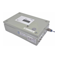
PowerLossMonitor PLM
10 Measurement
Please observe the safety instructions in Chapter 1 on page7.
10.1 Display the measuring values in the display or the PowerMonitorSoftware PMS
The measured values are displayed on the integrated display or can also be displayed on a PC via the
PRIMES bus or the USB-interface. This requires the PRIMES PowerMonitorSoftware PMS (included in the
scope of delivery).
10.2 Measuring value display
The following measuring values are displayed:
• Absolute temperature
• Temperature difference
• Flow rate of the cooling agent
• Calculated power loss
10.3 LED „Error“
The red LED glows if the water flow rate is too low.
Switch the laser off in this case and check the minimum flow-through volume.
10.4 Tare weight compensation to balance out various resistance values of the tempera-
ture sensors
For technical reasons, different resistance values in the temperature sensors can occur (depending on
the cable length and the contact resistance), which can lead to different power displays when the laser is
switched off.
The PRIMES PowerMonitorSoftware PMS offers the possibility to adjust this „offset“ before a measurement
(tare adjustment).
Click on the button Use current value as offset before measurement.
Fig. 10.1: User interface of the PowerMonitorSoftware PMS
 Loading...