17
Revision 01/2019 EN
PowerLossMonitor PLM
8 Electrical connection
The measuring device has the following electrical connections:
• Connection for the external temperature sensor (T-Sensor external)
• Safety interlock connection in order to control the water flow rate (safety Interlock and safety interlock
MSM respectively)
• PRIMES bus connections (D-Sub sockets, 9-pin) for the power supply and communication
• USB interface
• Analog output 0V ... 10V
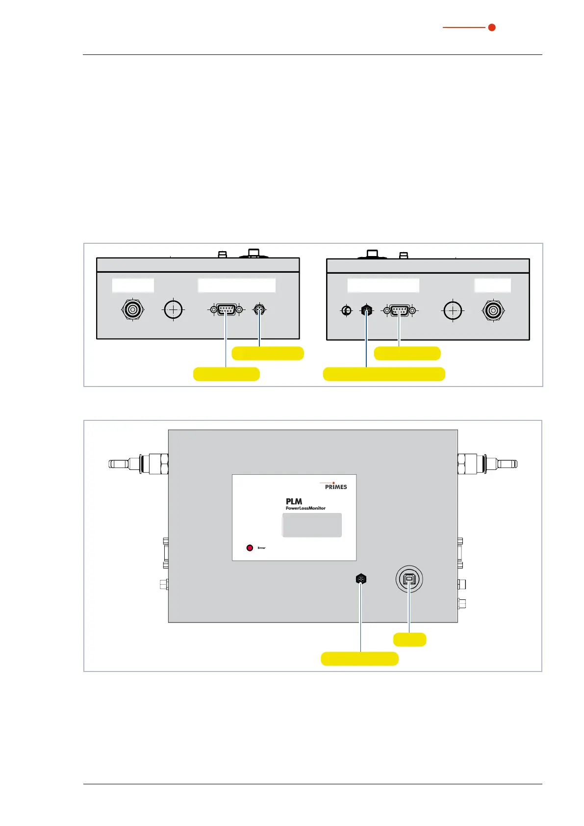
8.1 Electrical connections on the PLM 2
Water In
from Chiller
PRIMES-Bus
RS485
Safety
Interlock
T-Sensor
external
PRIMES-Bus
RS485
Water Out
to Absorber
External temperature sensor
PRIMES bus
PRIMES bus
Safety interlock
Fig. 8.1: Electrical connections PLM 2 at the side
USB
Analog output
Fig. 8.2: Electrical connections PLM 2 at the cover plate
 Loading...