24
Revision 01/2019 EN
PowerLossMonitor PLM
8.10 Analog output
The analog signal is effected via the 4-pin device socket M8 (see Fig. 8.2 on page17 or Fig. 8.4 on
page18 and Fig. 8.5 on page19). The output voltage is 0V ...10V. A suitable connection cable is
included in the scope of delivery.
PLM 2 PLM 10 PLM 20 PLM 40
An output voltage of 1V equals approx. 250W 1000W 2000W 4000W
Tab. 8.3: Output voltage and laser power
Pin assignment socket
(top view, plug-in side)
Pin Wire color Function
1 Brown Not connected
2 White Not connected
3 Blue Ground for the analog signal
4 Black Analog signal 0-10 Volt
Tab. 8.4: Socket assignment of the analog output
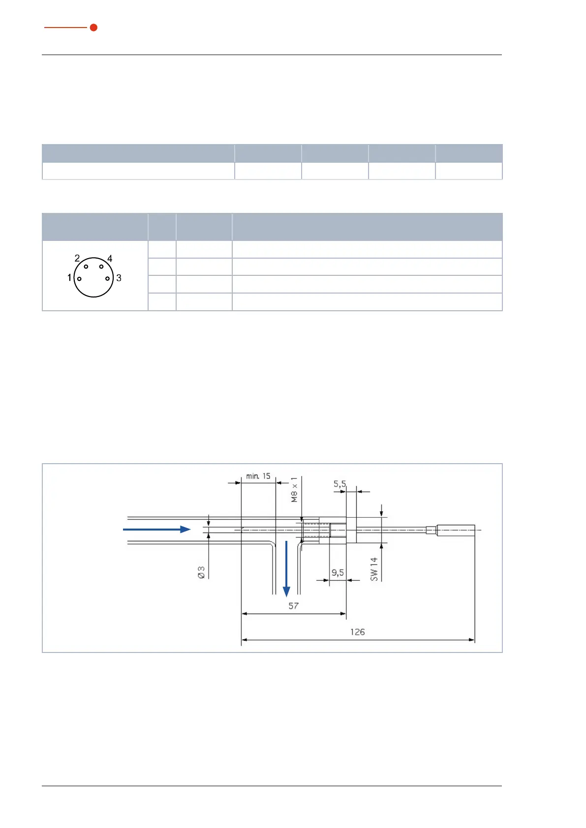
9 Installation of the external temperature sensor
The temperature sensor has to be installed in a way that ensures that it extends into the water flow but
against the flow direction. The tip should protrude from the bottom of the pipe approximately 15mm.
1. Plug the external temperature sensor into the cooling circuit output using a T-piece (see Fig. 7.4 on
page16).
X The temperature sensor should be positioned as close to the cooling circuit output of the mirror or the
absorber as possible.
Flow Direction
Fig. 9.1: Installation of the external temperature sensor
 Loading...