20
Revision 01/2019 EN
PowerLossMonitor PLM
8.4 Connect the safety interlock
The safety interlock protects the measuring device from damages by turning off the laser in case of an error.
The device can be damaged in case of a low water flow rate.
Whenever the water flow rate is too low, pins1 and 4 are connected. In case the water flow rate is according
to the operating conditions, pins1 and 3 are connected.
NOTICE
Damaging/Destruction of the device
If the safety interlock is not connected, this may lead to damages to the device due to over-
heating.
X
Make sure to connect the laser control in a way that ensures that the laser is turned off
whenever this connection is interrupted.
A suitable connection cable with a device plug and free ends is included in the scope of delivery
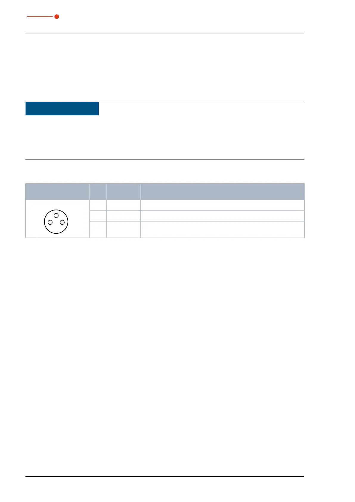
Pin assignment socket
(top view, plug-in side)
Pin Wire color Function
13
4
1 Brown Mutual pin
3 Blue Connected with Pin1 when ready for operation
4 Black Connected with Pin1 when in safety interlock mode
(water flow rate too low)
Tab. 8.1: Pin assignment safety interlock
 Loading...