15
Revision 01/2019 EN
PowerLossMonitor PLM
7.4 Water connections and water flow rate
The devices have the following outside port diameters. To ensure a reliable operation, the water flow rate ac-
cording to Tab. 7.2 on page15 is required. When the minimum flow rate is not met, the laser will be turned
off if a safety interlock is connected.
PLM 2 PLM 10 PLM 20 PLM 40
Connection outer diameter for PE hoses 8mm 12mm 16mm 3/4Zoll
Recommended flow rate in l/min 1 – 4 7 – 12 10 – 22 20 – 37
Minimum flow rate in l/min 0.5 4 4 8
Tab. 7.2: Water connection outer diameter and cooling water flow rate
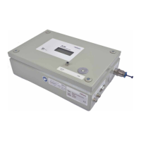
7.5 Cooling circuit connections on the PLM 2
Outside port diameter for PE hose 8mm
Water In
from Chiller
PRIMES-Bus
RS485
Safety
Interlock
Water connection from chiller
T-Sensor
external
PRIMES-Bus
RS485
Water Out
to Absorber
Water connection to mirror
Fig. 7.1: Water connections PLM 2
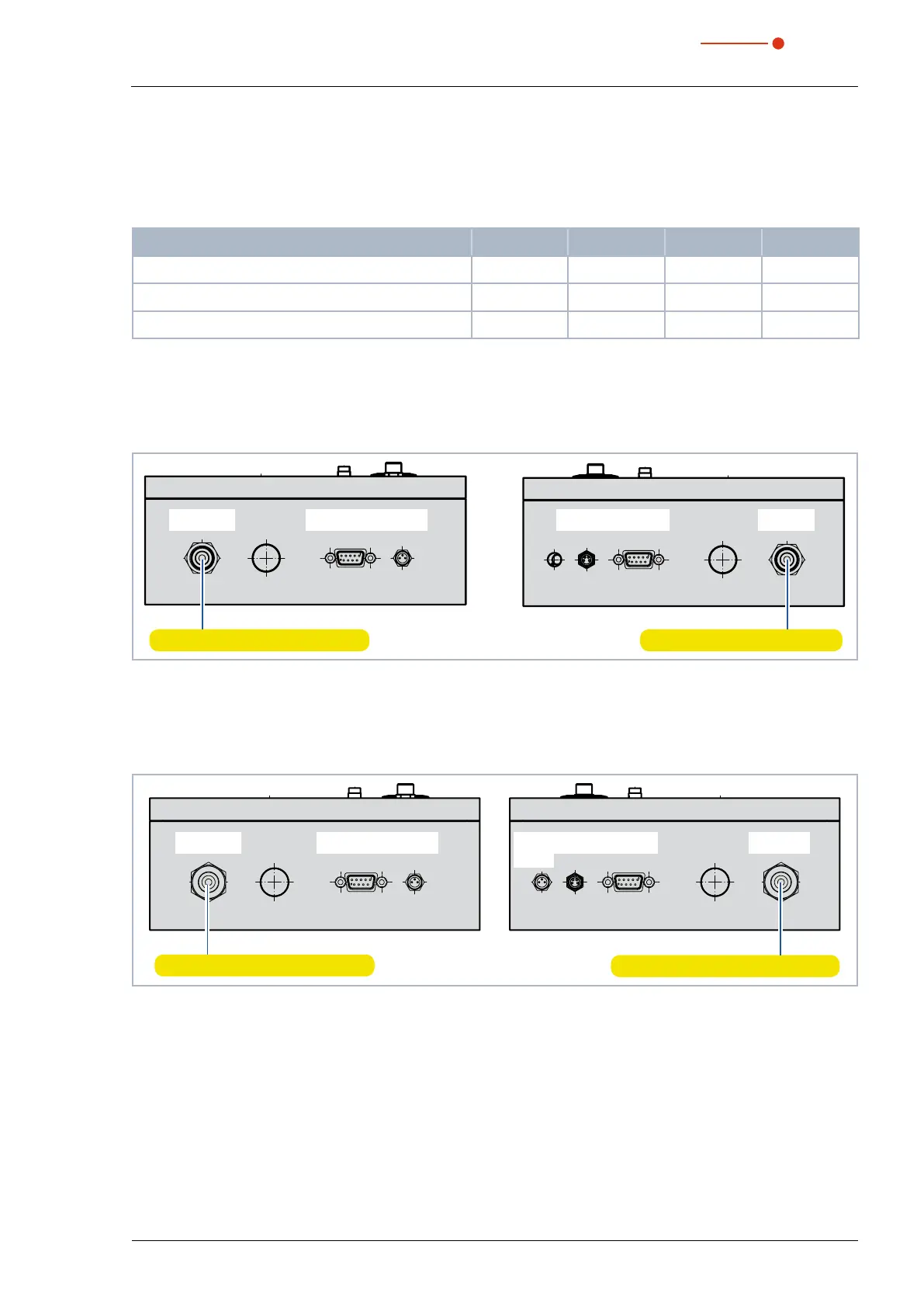
7.6 Cooling circuit connections on the PLM 10 and PLM 20
Outside port diameter for PE hose 12mm (PLM 10) and 16mm (PLM 20)
Water connection to absorber
T-Sensor
external
PRIMES-Bus
RS485
Water Out
to Absorber
Safety
Interlock
MSM
Water In
from Chiller
PRIMES-Bus
RS485
Safety
Interlock
Water connection from chiller
Fig. 7.2: Water connections PLM 10 and PLM 20
 Loading...