4
Revision 01/2019 EN
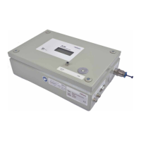
PowerLossMonitor PLM
Table of contents
1 Basic safety instructions 7
2 Symbol explanations 9
3 Conditions at the installation site 9
4 Introduction 10
4.1 System description .................................................................................................................10
4.2 Measuring principle .................................................................................................................10
4.3 Configurations ......................................................................................................................... 11
5 Transport 12
6 Installing the software 12
7 Connecting the cooling circuit 13
7.1 Water quality ...........................................................................................................................13
7.2 Water pressure ........................................................................................................................ 13
7.3 Humidity ..................................................................................................................................14
7.4 Water connections and water flow rate ....................................................................................15
7.5 Cooling circuit connections on the PLM 2 ...............................................................................15
7.6 Cooling circuit connections on the PLM 10 and PLM 20 .........................................................15
7.7 Cooling circuit connections on the PLM 40 .............................................................................16
7.8 Influence of the hose lengths on the time constants for measuring devices with external
temperature sensor .................................................................................................................16
8 Electrical connection 17
8.1 Electrical connections on the PLM 2........................................................................................17
8.2 Electrical connections on the PLM 10 and PLM 20 .................................................................18
8.3 Electrical connections on the PLM 40......................................................................................19
8.3.1 Toggle switch to switch between external and internal temperature sensor ...............19
8.4 Connect the safety interlock ....................................................................................................20
8.5 Connect the power supply ......................................................................................................21
8.6 PIRMES bus ............................................................................................................................21
8.7 Connect the external temperature sensor ................................................................................ 21
8.8 Connect the PC via the RS232 interface .................................................................................22
8.9 Connect the PC via the USB interface .....................................................................................23
8.10 Analog output .........................................................................................................................24
9 Installation of the external temperature sensor 24
10 Measurement 25
10.1 Display the measuring values in the display or the PowerMonitorSoftware PMS ......................25
10.2 Measuring value display ..........................................................................................................25
10.3 LED „Error“ .............................................................................................................................25
10.4
Tare weight compensation to balance out various resistance values of the temperature sensors 25
11 Storage 26
12 Maintenance and service 26
13 Measures for the product disposal 26
14 Declaration of conformity 27
15 Technical data 28

 Loading...