Do you have a question about the Primes PowerLossMonitor PLM Series and is the answer not in the manual?
Device purpose and adherence to specifications.
Adherence to national and international safety regulations.
Safety measures for laser radiation danger zones.
Requirement for qualified personnel operation.
Prohibition of device modification without permission.
Explanation of danger, warning, caution, notice symbols, and CE marking.
Device must not be in condensing atmosphere, air must be clean, protected from water/dust, and used in closed rooms.
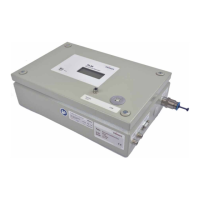
System overview and purpose of PLM.
How the device measures power loss using water flow and temperature.
Available device configurations and connections.
Precautions against damage from hits, falls, and freezing water.
Steps to install the PowerMonitorSoftware PMS on a PC.
Guidelines on acceptable cooling water types and chemical potentials.
Maximum allowable water pressure for different PLM versions.
Humidity constraints and dew point control for condensation prevention.
Port diameters and required flow rates for reliable operation.
Visual guides for connecting cooling circuits on PLM models.
Impact of hose length on measurement time constants.
Identification of electrical connection points on the PLM 2 model.
Identification of electrical connection points on PLM 10/20 models.
Identification of electrical connection points on the PLM 40 model.
How to switch between external and internal temperature sensors.
Connecting the safety interlock for error control and laser shutdown.
Connecting the 24V DC power supply unit.
Using the 9-pin D-Sub for power and communication.
Connecting the Pt100 four-wire temperature sensor.
Connecting the PC using the RS232 interface and converter.
Connecting the PC using the USB interface.
Analog output voltage mapping to laser power.
How to install the sensor into the cooling circuit for accurate measurement.
How measured values are shown on the device or PC software.
List of absolute temperature, difference, flow rate, and power loss.
Meaning of the red LED indicating low water flow rate.
Using software to compensate for sensor resistance variations.
Guidelines for storing the device to prevent damage from water.
Suggestion for 12-month inspection, validation, or calibration.
Information on free disposal of PRIMES devices within the EU.
Statement of compliance with relevant EC Directives.
Max laser power, resolution, and temperature measurement specs.
Power supply voltage, current demand, and pressure ratings.
Available communication ports (RS485, USB).
Physical dimensions and approximate weight of models.
Detailed physical dimensions of the PLM 2 model.
Detailed physical dimensions of the PLM 10 model.
Detailed physical dimensions of the PLM 20 model.
Detailed physical dimensions of the PLM 40 model.
| Category | Measuring Instruments |
|---|---|
| Series | PLM Series |
| Type | Power Loss Monitor |
| Display | LCD |
| Frequency Range | 45Hz to 65Hz |
| Communication Interface | RS485 |
| Power Supply | 85-265 VAC |
| Operating Temperature | -10 to 50°C |
| Storage Temperature | -20°C to 70°C |