Chapter 9 Maintenance
9-25
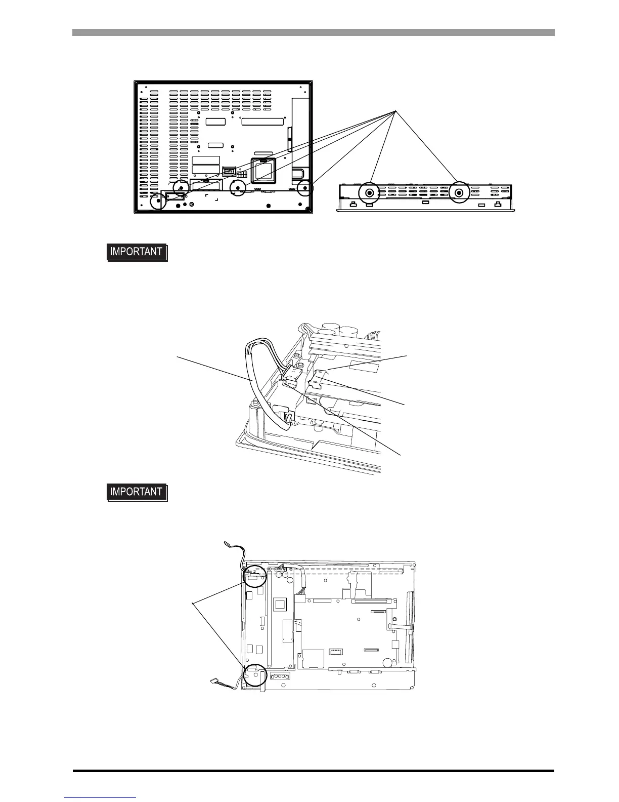
(2) Remove the retaining screws (6) on the rear cover, and detach the cover from the main unit.
(3) Pull out cable from inverter insulating sheet, and remove from cable clump.
Remove cable from backlight connector on inverter circuit board.
(4) Insert shuttle driver to circular hole, and remove backlight setscrew. There are two circular hole.
• Do not let the attachment screws fall inside the GP, or lose them.
• A hot circuit board chassis can burn you. Be sure the chassis has cooled completely
prior to replacing the backlights.
Retaining screws
Rear
Upper
Cable
Cable clump
Backlight connector
Inverter insulating sheet
Shuttle driver entry




 To Next Page