GP3000 Series Hardware Manual
3-2
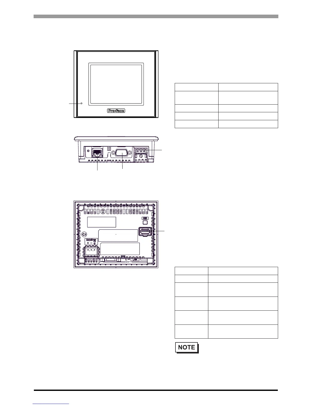
3.1 GP-3200 Series
A: Status LED
This LED indicates the GP’s status, e.g. power
input, firmware RUN status or backlight condition.
Also, indicates the status of logic program
execution.
B: Power Plug Connector
C: USB Host Interface
Complies with USB 1.1. Uses a “ TYPE-A”
connector. Power supply voltage: 5VDC
±5%,
Output current: 500mA(max). The maximum
communication distance : 5m.
D: Serial Interface (COM1)
RS232C/RS422/RS485 serial interface. D-sub 9-
pin plug type connector. Communication method is
switched via software.
E: Ethernet Interface
(10BASE-T/100BASE-TX)
The Ethernet transmission interface (10BASE-
T/100BASE-TX).
An RJ-45 type modular jack connector (8-pole)
is used. The LED turns on or off to indicate the
current status.
LED Indicates
Green ON
Normal operation (power is
ON.) or OFFLINE operation.
Orange Flashing During software startup
Red ON When power is turned on.
OFF No Power
LED Indicates
Green ON Data transmission available
Green
Flashing
Data transmission is
occurring.
Green OFF
No connection or subsequent
transmission failure
Yellow ON
During connection with
100BASE-TX
Yellow OFF
During connection with
10BASE-T or No connection
• Do not remove or insert the CF
Card when the LED lamp is on.
Doing so may damage data on the
CF Card.
Front
Back
A
B
C
Bottom
D
E
 Loading...