GP3000 Series Hardware Manual
9-26
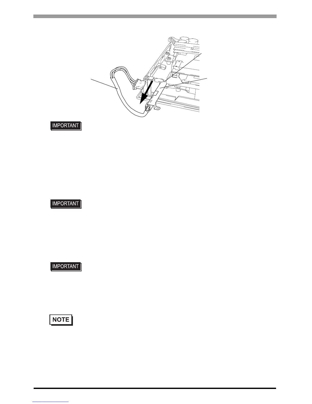
(5) Drawn out the cable in the direction of an arrow. Creep out backlight unit from backlight unit slot.
(6) Insert a new backlight unit in backlight unit slot.
Secure the backlight setscrew. The necessary torque is 0.147N•m. (The procedure of opposite to proce-
dure 4.)
(7) Insert the cable to backlight connector.
Secure the cable with the cable clamp.
(The procedure of opposite to procedure 3.)
(8) Return the rear face cover to the original position, and secure the cover in place using the mounting
screws (6). The necessary torque is 0.5N•m
• Replace backlight the whole backlight unit.
• Be sure the cable is inserted completely into the backlight connector. Failure to do so
may cause arcing, which can damage the connector.
• Backlight has used 1 each of top and bottom LCD. The case of exchange 2 please
exchange simultaneously.
• The cable clamp is used to prevent the cable from being caught inside in the GP unit
and possibly damaged. Be sure to insert the cable in the cable clamp around the
cable before replacing the rear cover.
• If any of the screws is missing, check if it fell inside the GP unit’s chassis. If the
power is turned ON while a screw is inside, it may cause an accident or fire.
• After backlight replacement is completed, turn the GP unit’s power ON and check if the screen’s
display is normal. If the display is not correct, please contact the GP distributor from whom you
purchased the backlight unit.
Backlight Unit
Backlight Unit slot
Cable




 To Previous Page