14
M-43-25 LUF-Series Lufran Manual
Revision - Date 03-01-04-18 Standard outlet, Standard Interface
Engineering Information (Continued):
Optional Communications (Continued):
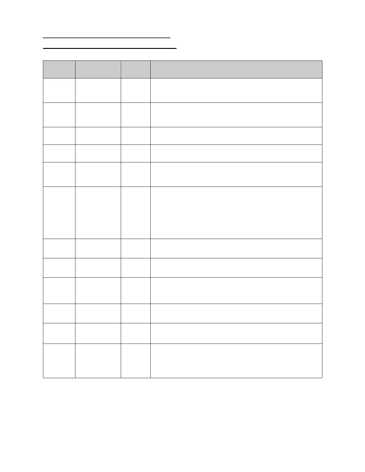
The following table describes the network addresses of the Lufran water heater.
Network
Data Signal
Description
V3200
Inlet water
temperature
(°C)
Heater
output
The value provided is the measured inlet water temperature.
V3202
Outlet water
temperature
(°C)
Heater
output
The value provided is the measured outlet water temperature.
This address may be used to monitor the outlet temperature of
the heater through the network.
V3204
Flow rate
(liters/min)
Heater
output
The value provided is the measured water flow rate through
the heater.
V3206
Heater output
(%)
Heater
output
The value provided is the current percentage (%) output of the
heating column(s).
V3210 Set point (°C)
Heater
output
The value provided is the outlet set point of the heater. When
the system is in NETWORK control mode, this value should
match address V3102.
V3212
Remote
control
Heater
output
0 = System is in LOCAL control mode
1 = System is in MANUAL control mode
2 = System is in REMOTE control mode
3 = System is in NETWORK control mode
This setting is adjusted in the control access menu, through
the operator interface touch screen.
V3214
System
enabled
Heater
output
0 = System disabled
1 = System enabled
V3216
System
operating
Heater
output
0 = Not operating
1 = Operating
V3220
System at
temperature
Heater
output
0 = Outlet temperature is not within the process deviation
setting
1 = Outlet temperature is within the process deviation setting
V3222 System fault
Heater
output
0 = No system fault detected
1 = System fault detected
V3100
Remote
start/stop
Heater
input
0 = Stop heater operation
1 = Start heater operation
V3102
Heater set
point (°C)
Heater
input
The value provided from the network to the heater will be
the desired outlet set point of the heater. When the
system is in NETWORK control mode, this value should
be matched by address V3210.