24
M-43-25 LUF-Series Lufran Manual
Revision - Date 03-01-04-18 Standard outlet, Standard Interface
Engineering Information (Continued):
Operator Interface Panel (OIP) (Continued):
Configuration Menu (Continued):
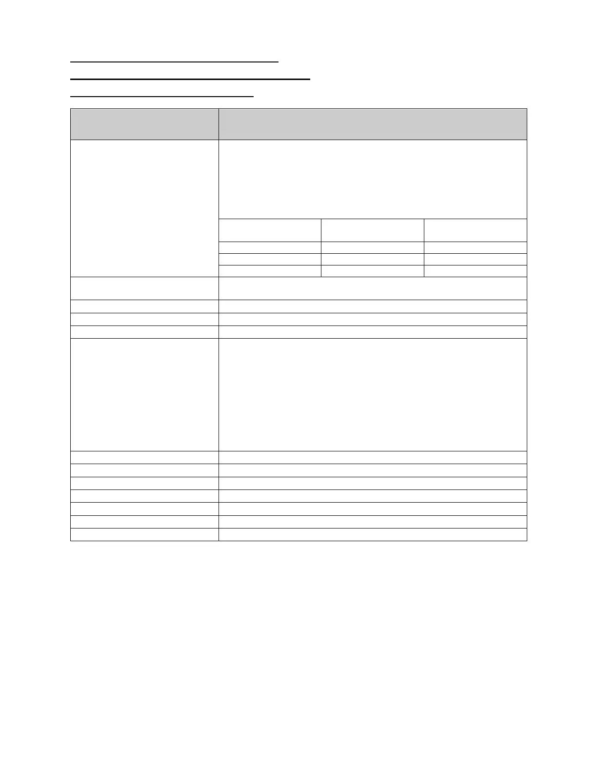
Configuration Menu
Description
LOW FLOW SETPOINT
Displays the LOW FLOW SETPOINT. This setting will disable heater
operation
when the flow rate through the heater falls below this
setting (liters per minute). The controller will provide a warning
message when the flow rate has dropped below this setting, but it
will not enter an alarm state. When the flow rate through the heater
has risen above the value of this setting heater operation will
continue. This setting is factory set to the valued listed below:
Heater Wattage
Number of Heating
Columns
HEATER SIZE
Displays the heat output of the unit. This value is necessary for
proper operation of the DAC control system. This is a factory setting.
This button displays the FLOW CALIBRATION screen.
This button will reset all values to factory settings.
This button displays the HEATER CALIBRATION screen.
BOOST GAIN
This button allows adjustment of the BOOST GAIN. This setting
improves heater performance during initial temp rise from a low
temperature. This setting has a range of 0-
factory set during testing. By increasing the value of this setting (by
increments of 1), the heater will increase the rate of temperature rise
from a low temperature. Note however that increasing the value of
this setting will result in a temperature overshoot as the heater outlet
temperature reaches the process setpoint. The default value will
provide the quickest rate of temperature rise with no temperature
overshoot above the process setpoint.
This button will display the MAIN MENU screen.
This button will display the ADAM SETUP MENU screen.
This button will display the SLC SETUP MENU screen.
This button will display the TC1 SETUP MENU screen.
This button will display screen 2 of the CONFIGURATION MENU
This button will display the HEATER CALIBRATION MENU screen.
This button will return to the previous screen.