25
M-43-25 LUF-Series Lufran Manual
Revision - Date 03-01-04-18 Standard outlet, Standard Interface
Engineering Information (Continued):
Operator Interface Panel (OIP) (Continued):
TC1 Setup Menu:
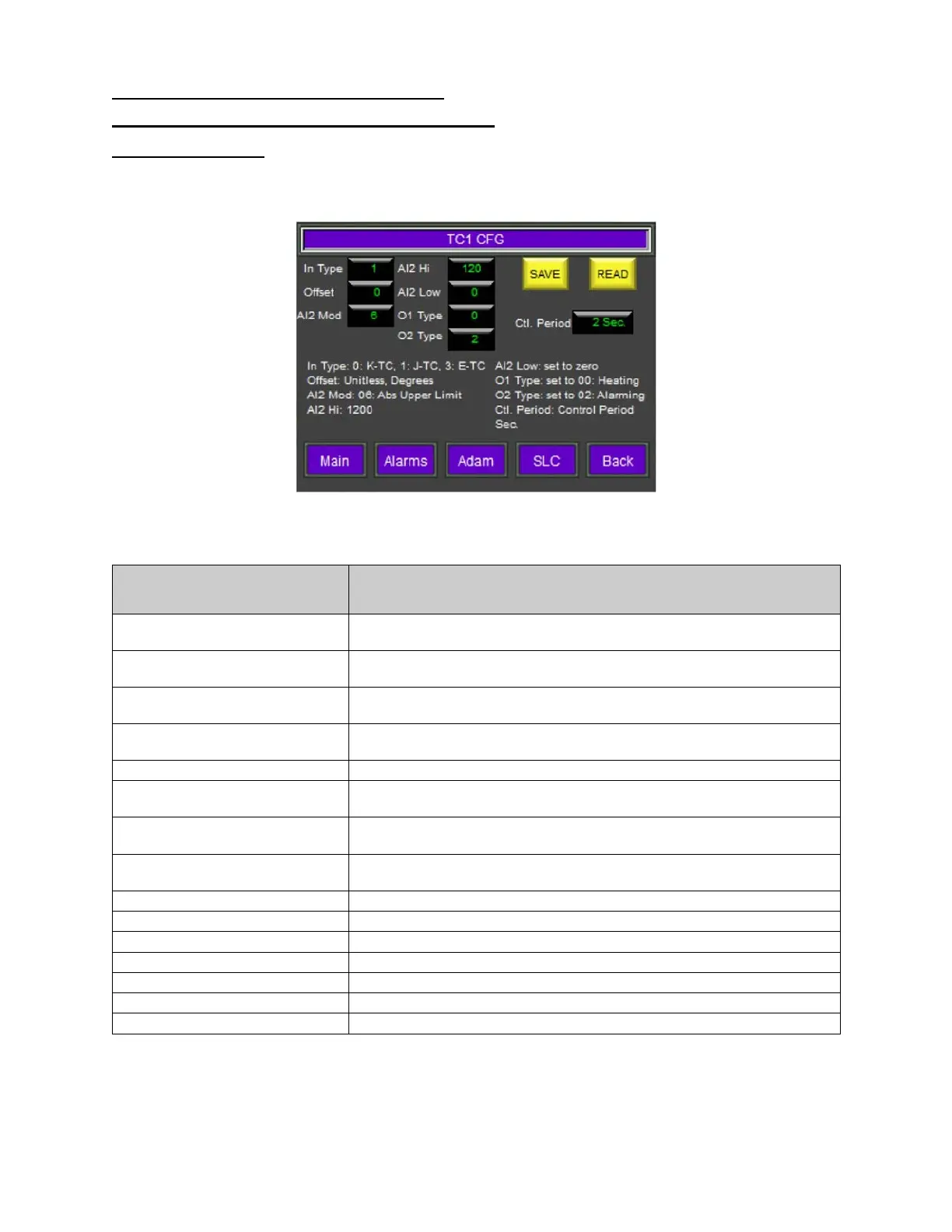
This menu displays the various settings for the temperature control module. This module controls the
switching of the solid state relays.
Figure 15: TC1 Setup Menu
TC1 Setup Information
Description
IN TYPE
This field identifies the sensor input type. This is a factory setting
which should not be changed.
OFFSET
Sensor offset value. The range is -10 to +10.
Press the offset button to bring up a keypad to change its value.
AL2 MOD
Alarm 2 function. Value 6= absolute upper limit alarm. This is a
factory setting which should not be changed.
AL2 HI
Alarm high limit value. This setting triggers the PROCESS
OVERTEMP alarm.
Alarm low limit value. (Not used)
O1 TYPE
Output 1 type. Value 00 = heating. This is a factory setting which
should not be changed.
O2 TYPE
Output 2 type. Value 02 = Alarm. This is a factory setting which
should not be changed.
CTL PERIOD
Displays the control time period. The range for this setting is 1-30
seconds. This is a factory setting which should not be changed.
Saves changes made to a TC1 value.
Reads the stored value from the TC1 module’s memory.
This button will display the MAIN MENU screen.
This button will display the ALARMS MENU screen.
This button will display the ADAM SETUP MENU screen.
This button will display the SLC SETUP MENU screen.
This button will return to the previous screen.