22
M-43-25 LUF-Series Lufran Manual
Revision - Date 03-01-04-18 Standard outlet, Standard Interface
Engineering Information (Continued):
Operator Interface Panel (OIP) (Continued):
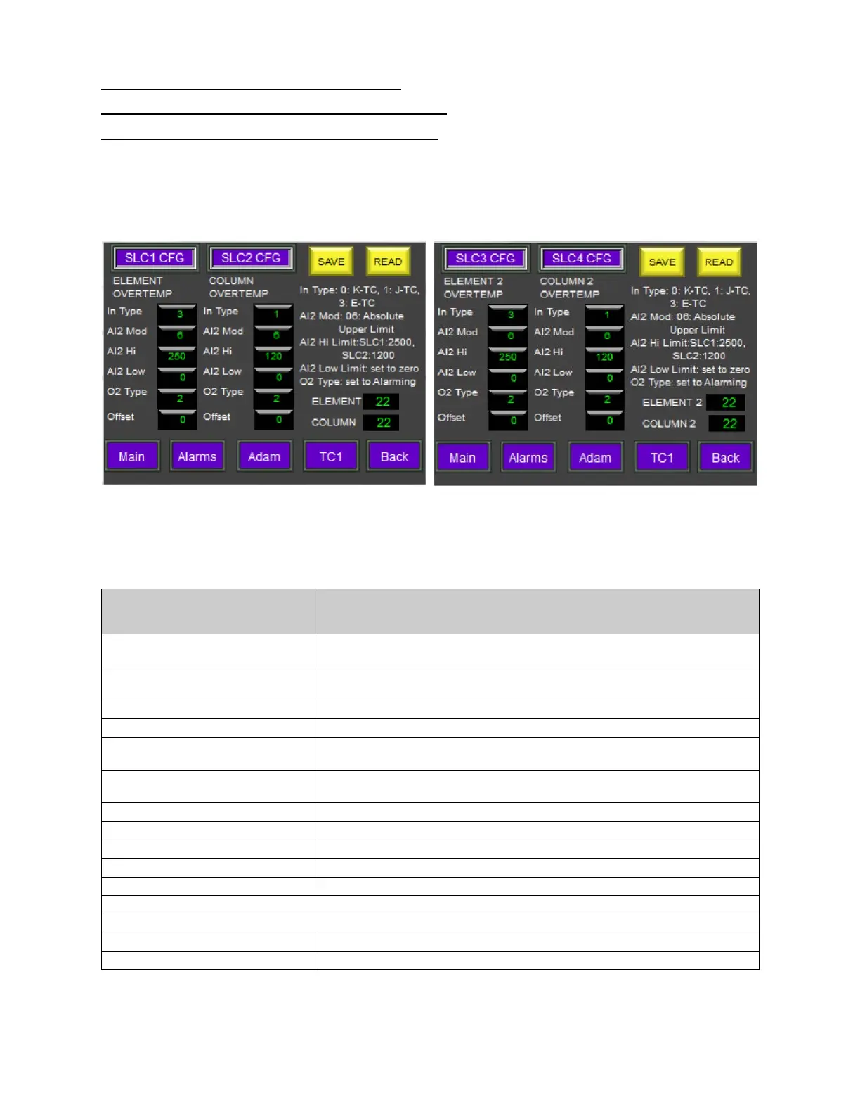
Safety Limit Controller (SLC) Setup Menu:
This menu displays the various settings for the safety limit controller modules #1 through #8. SLC1,
SLC3, SLC5 and SLC7 modules monitor the heating element sensors in heating columns 1 through 4,
respectively. SLC2, SLC4, SLC6 and SLC8 modules monitor the temperature sensors inside of heating
columns 1 through 4, respectively. Additional SLC Setup menu screens will be present for heaters with 3-
4 columns.
(SLC1-SLC2, for column 1) (SLC3-SLC4, for column 2)
(SLC menu screens for columns 3-4 not shown)
Figure 13: SLC Setup Menu
SLC Setup Information
Description
IN TYPE
This field identifies the sensor input type. This is a factory setting
which should not be changed.
AL2 MOD
Alarm 2 function for each module. Value 6= absolute upper limit
alarm. This is a factory setting which should not be changed.
Alarm high limit value for this alarm in each module.
Alarm low limit value for this alarm in each module. (Not used)
O2 TYPE
Output 2 type for each module. Value 2=set to alarming. This is a
factory setting which should not be changed.
OFFSET
Sensor offset value for each module. The range is -10 to +10.
Press the offset button to bring up a keypad to change its value.
Saves changes made to an SLC value.
Reads the stored value from the SLC module’s memory.
Displays current value measured by SLC1.
Displays current value measured by SLC2.
This button will display the MAIN MENU screen.
This button will display the ALARMS MENU screen.
This button will display the ADAM SETUP MENU screen.
This button will display the TC1 SETUP MENU screen.
This button will return to the previous screen.