53
M-43-25 LUF-Series Lufran Manual
Revision - Date 03-01-04-18 Standard outlet, Standard Interface
Maintenance Procedures (Continued):
Procedure M6-2: PRV Replacement Procedure (Continued):
5) Disconnect the ½-inch fluoropolymer discharge tube by loosening and removing the compression
fitting on the PRV.
6) Unscrew and remove the PRV by turning the PRV body counter-clockwise.
7) Inspect the O-Ring located in the inlet manifold for any damage.
8) Screw the new PRV into the inlet manifold connector.
Note: Do not disturb the setting of the gray pvc adjustment cap. Do not over-tighten the compression
fitting.
9) Re-connect the ½-inch discharge tubing to the PRV.
10) Start flow of water to the unit and check for leaks.
11) Close the rear cabinet door.
M7: Cabinet Cooling Fans
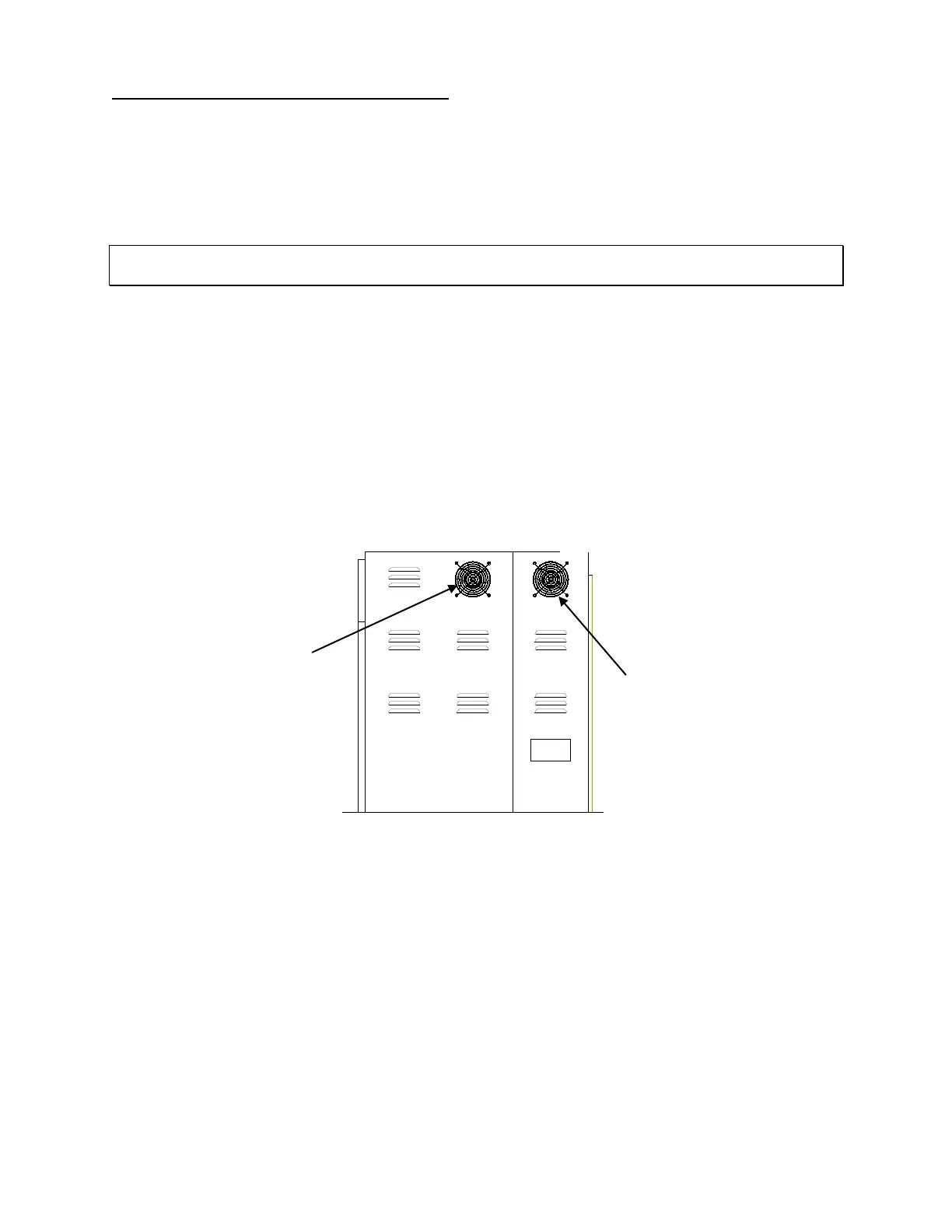
There are two cooling fans located in the heater cabinet. Both fans are located on the left side of the unit,
near the top. One cooling fan is mounted in the electrical side, and one cooling fan is located in the
plumbing side of the cabinet. These cooling fans should be operating continuously while power is
applied.
The cooling fans should be replaced every 24-months.
Figure 39: Cabinet Cooling Fans
Procedure M7-1: Cooling Fan Inspection Procedure:
Verify that the cooling fans are operating. If a cooling fan has stopped, it must be replaced.
Cooling fan for electrical side
of unit
side of unit