5
M-43-25 LUF-Series Lufran Manual
Revision - Date 03-01-04-18 Standard outlet, Standard Interface
Engineering Information (Continued):
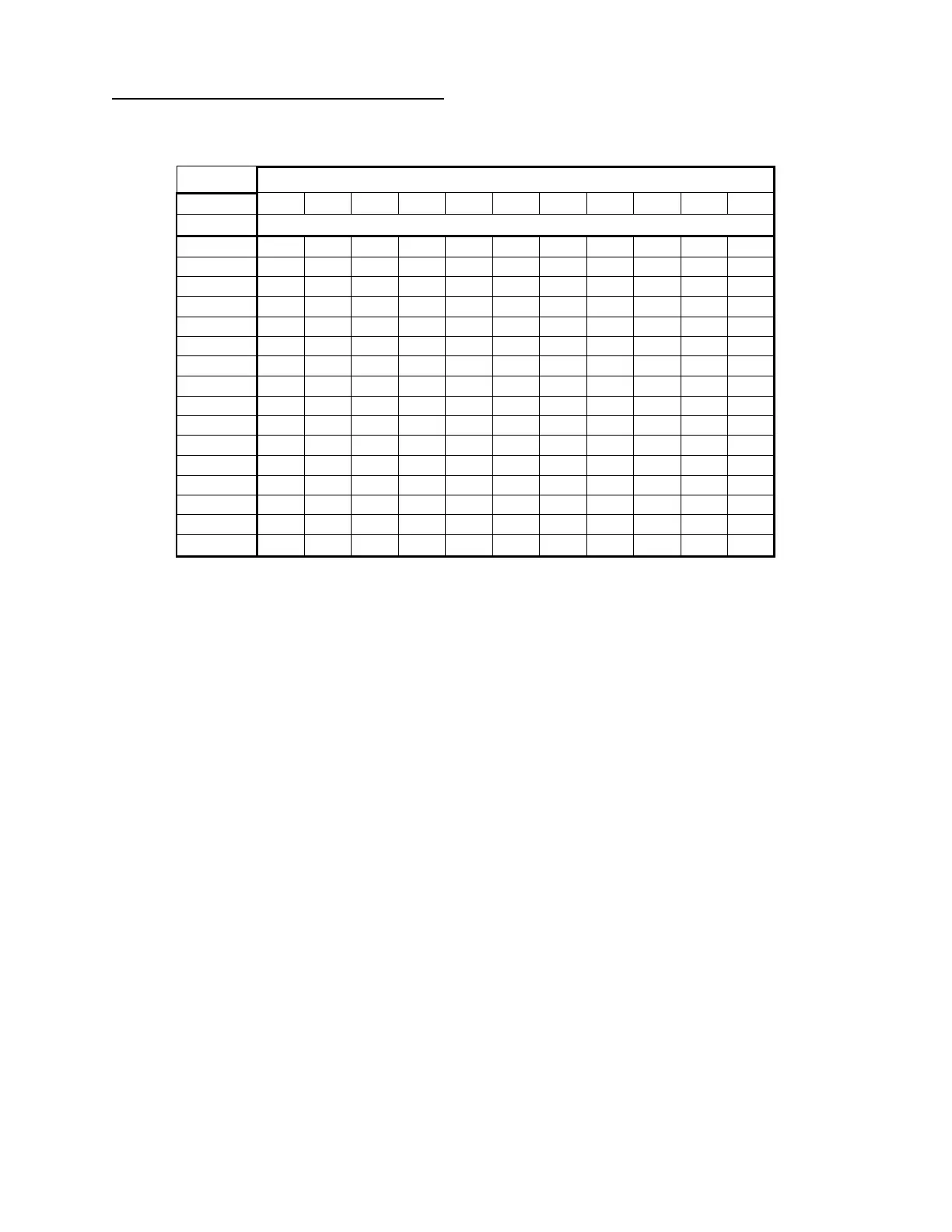
The maximum possible temperature rise through the heater is dependent upon the wattage of the unit
and the water flow rate through the unit. The following table illustrates the maximum temperature rise of
various models based upon the water flow rate through the unit.
The Lufran fluoropolymer inline water heaters include a comprehensive system of safety controls and
devices to insure safe and long-lasting operation. The list of safety devices includes but is not limited to
the following:
• EMO pushbutton
• Circuit breaker
• Ground fault (earth leakage) protection
• Pressure relief valve
• Liquid level sensor
• Leak detector (optional)
• High process temperature sensor
• High element temperature sensor
• Purge gas flow switch
• Moisture sensor in the purge gas exhaust line
• Sensor failure (open sensor) detection
Heater Power (Kilowatts)
Maximum Theoretical Temperature Rise (°C)