3736
SYSTEM VOLTAGE
The PF2100 is designed to operate with a nominal 12VDC or 24VDC Power Supply. The system will not
be damaged by applying any voltage in or near this range regardless of menu settings. Note that attached
valves are typically not designed to accept both 12VDC and 24VDC. If the valve voltage ratings are
exceeded, the valves may become damaged.
System Voltage Setting (Menu 4)
This setting defines voltage limits to protect and allow the proper operation of the attached
valves. If the PF2100 detects that the input voltage is getting close to these limits, it will
display a warning message. If the voltage exceeds these limits, the system will shut down
and cut power to the valves.
The following options are available:
VOLTAGE SETTING CHOOSE THIS OPTION WHEN…
12 V The Power Supply and all valves are 12 VDC
24 V The Power Supply and all valves are 24 VDC
The exact limits used are shown in the following table. Note that the high voltage limits also depend on
the Pilot Valve Power Setting and Main Valve Power Setting which can also be found in Menu 4.
V SETTING PILOT / MAIN VALVE PWM SETTING LOW V ALARM LOW V WARNING HIGH V WARNING HIGH V ALARM
12V At least one equal to 100% <= 8.4V <= 9.9V >= 14.6V >= 15.6V
12V Both less than 100% <= 8.4V <= 9.9V >= 16.1V >= 16.8V
24V At least one equal to 100% <= 17.9V <= 19.9V >= 28.6V >= 30.0V
24V Both less than 100% <= 17.9V <= 19.9V >= 33.1V >= 40.0V
PROCESS CONTROL SETTINGS
For the PF2100, Process Control refers to controlling the temperature of a process. This process usually
involves heating fluid in a tank or pipe. A primary temperature control signal is required for Process
Control. This is called the Process Temperature or Proc Temp. Optionally, an auxiliary temperature control
signal can also be accepted. This signal is called the Auxiliary Temperature or Aux Temp.
Note that these two signals are not necessarily the same as Proc TC and Aux TC which are the names of
the physical thermocouple inputs on the Terminal Card. The Aux Temp signal is only compared to the Aux
Setpoint, if enabled.
There are four settings that directly affect Process Control: Process Control Input, Low Fire Enable, Pilot
Off Enable, and Aux Temp Mode.
Note that changing any of these settings may cause the Process setpoints (High Temp ESD, Pilot Off,
Low Fire, Process, Low Temp Alarm, Deadband, and Aux) to reset to factory defaults. A warning message
will display if this occurs.
Process Control Input (Menu 5)
This setting selects which thermocouple inputs will be used as the primary and auxiliary
temperature control signals as shown in the following table.
SETTING PROC TEMP AUX TEMP
Proc TC Proc TC Aux TC
Aux TC Aux TC Proc TC
In previous firmware versions this could also be set to Disabled. In this case, Process Control
was disabled and the system allowed the burner to always be lit and running. The typical
use for this was to have an external device, such as a PLC, controlling the process. The
PLC would turn the system on and off using the Start contacts. This behaviour can still be
achieved by setting all Process Setpoints to maximum.
Low Fire Enable (Menu 5)
This setting is used to toggle the use of the Low Fire Setpoint for Primary Process Control.
Low Fire can be enabled in two different modes: “On at Proc Setpoint” and “On at Low
Fire Setpoint”. In the first case, the Low Fire Valve will close when it exceeds the Low Fire
Setpoint but will not reopen until it drops below the Process Setpoint minus Deadband. In
the second case, the Low Fire Valve will close when it exceeds the Low Fire Setpoint and will
reopen after it drops below the Low Fire Setpoint minus Deadband.
Pilot Off Enable (Menu 5)
This setting is used to enable/disable use of the Pilot Off Setpoint for Primary Process
Control.
Aux Temp Mode (Menu 5)
When this setting is set to Temp Main Ctl, Auxiliary Process Control is enabled. See the
Auxiliary Temperature Settings section for more details.
PROCESS SETPOINTS
There are seven Process Setpoints in total, four of which may be disabled (hidden from menus). The order
of the setpoints varies depending on the value of the Process Control Input setting.
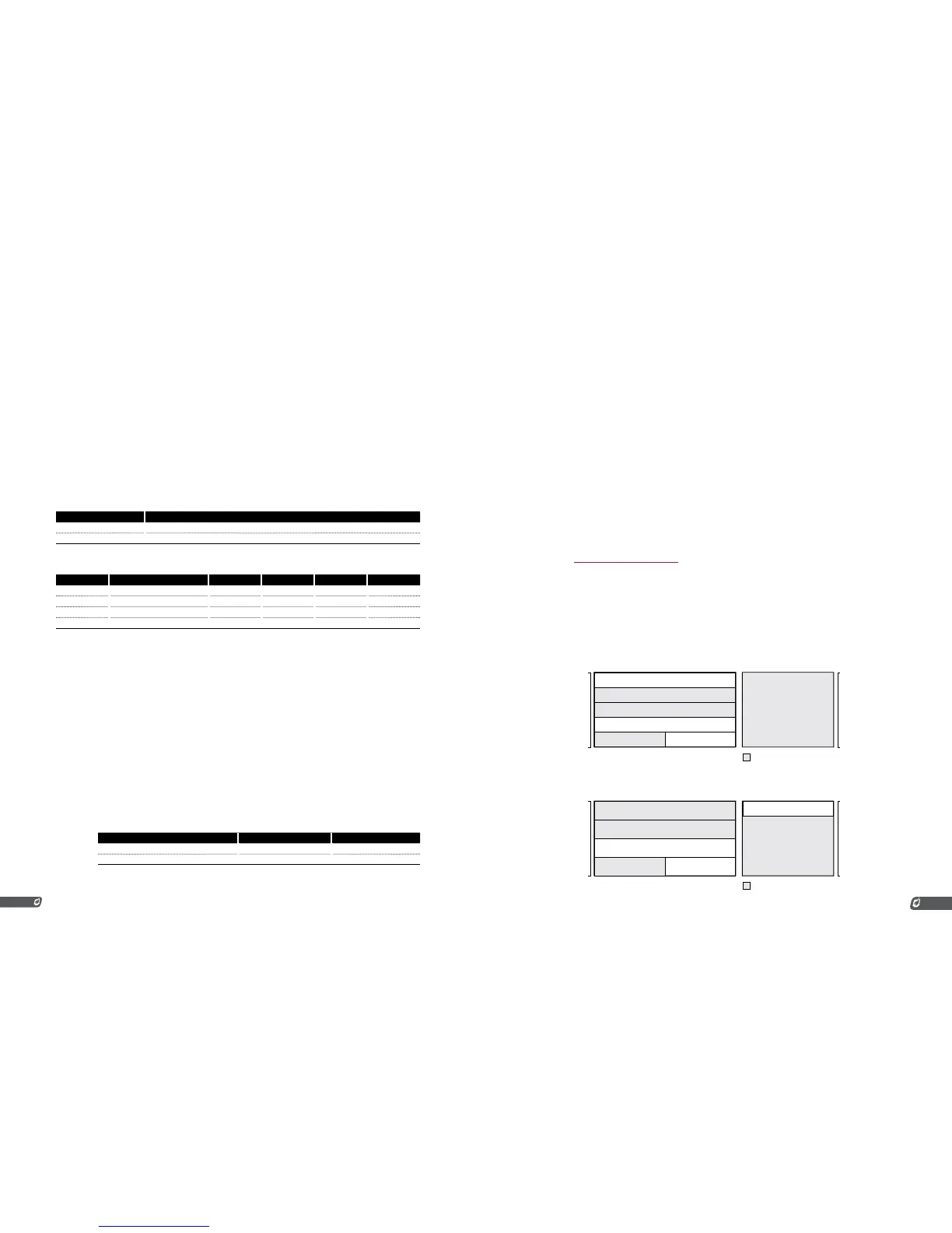
The following diagrams illustrate the upper and lower bounds of each setpoint and their order. Setpoints
that are shaded may be disabled. When a setpoint is disabled, the upper and lower bounds of the
adjacent setpoints are adjusted accordingly.
Process Control Input Setting: PROC TC
LOW TEMP ALARM
DEADBAND*
PROCESS SETPOINT
LOW FIRE SETPOINT
PILOT OFF SETPOINT
HIGH TEMP ESD SETPOINT
AUX SETPOINT
Setting can be hidden / disabled
Deadband Max = 150˚C