1716
5. Securely mount the enclosure to a pole, structure or building
as indicated by the site engineer or technician.
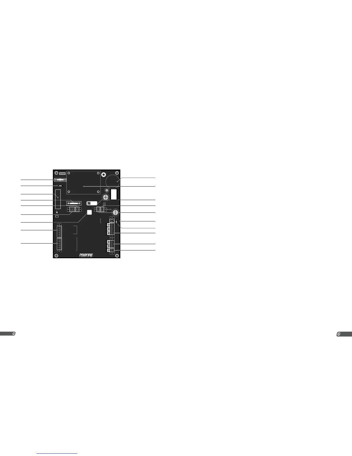
2.3 | Terminal Card Diagram
F2
SPARE FUSE
Status+
Status-
Start+
Start-
ESD+
ESD-
Proof of Closure+
Proof of Closure-
HighPressure+
HighPressure-
LowPressure+
LowPressure-
Level+
Level-
HighTemp_TC+ (Yellow)
HighTemp_TC- (Red)
Process_TC+ (Yellow)
Process_TC- (Red)
AUX_TC+ (Yellow)
AUX_TC- (Red)
High Fire+ / Main+
4-20mA Out-
4-20mA Out+
Earth Ground
Common
12/24VDC
Coil-
Coil+
Ion+
Ion-
High Fire- / Main-
Low Fire+
Low Fire-
Pilot+
Pilot-
1
2
3
6
5
4
XXXXXX-XXXXX
XXX-2.3.0
XXXXXX
SPARE FUSE
RESET
E
v1.8.005
INTERNAL COIL
IGNITION TERMINALS
STATUS CONTACT OUTPUT
HW SERIAL / VERSION LABEL
EXPANSION CARD SLOT
FLAME DETECTION TERMINAL
STATUS CONTACT FUSE
LEVEL DRY CONTACT INPUT
PRESSURE DRY CONTACT INPUTS
MISC. DRY CONTACT INPUTS
4-20mA OUTPUT
FW VERSION LABEL
THERMOCOUPLE INPUTS
MAIN FUSE
SPARE MAIN FUSE
SPARE STATUS CONTACT FUSE
DOOR CARD CONNECTOR
POWER TERMINALS
(optional expansion)
VALVE OUTPUTS
2.4 | Wiring
The wiring precautions in this section are important for all PF2100 installations. Please set up your
installations accordingly.
NOTE: If you have not wired a PF2100 system, please refer to the PF 2100 Install Guide for detailed
wiring instructions. Skipping or performing any steps in the guide incorrectly can result in the PF2100 not
functioning properly.
POWER
The PF2100 can be powered from 12VDC or 24VDC. The maximum current that the PF2100 can safely
handle without blowing the main fuse is 5A. The system on its own draws about 100mA. The rest of the
current is used by additional hardware such as valves. Make sure that you select a power supply that is
rated appropriately for the total amount of current that will be consumed by all devices attached to it.
VALVES
There are four valve control outputs on the PF2100: Pilot, Low Fire, 4-20mA Output, and High Fire/Main.
Ensure that each valve has a separate return wire. Multiple valves sharing common return wires will not
function properly.
Pilot Valve
The Pilot valve is required and must be wired for all installations.
Low Fire Valve
The Low Fire valve may also be required by local code or for proper operation of your
particular application. Low Fire is often used on high Btuh burners (burners that exceed 5
MM Btuh) to establish a draft before opening the High Fire valve. Failure to do this on high
Btuh burners can cause the burner to starve itself of oxygen which puts out the flame.
4-20mA Output
The 4-20mA Output can be used to control a proportional valve designed for a 4-20mA
current loop. Using a proportional valve allows for finer control of the burner’s temperature as
opposed to the 2 or 3 levels possible with normal valves. Typically the 4-20mA Output is used
in conjunction with a normal valve. The 4-20mA Output also supports low fire.
High Fire/Main Valve
The High Fire valve is required and must be wired for all installations. This valve is sometimes
called the Main Valve, especially when Low Fire is not used.
NOTE: It is possible to connect multiple valves to the same control output in parallel or series. If you do
this, be sure that the configuration you are using meets local codes and does not exceed the total current
rating of the PF2100.
NOTE: The negative valve control wires are NOT connected directly to ground. Therefore, you cannot use
a common return wire for all valves.
THERMOCOUPLES
The High Temp and Process thermocouple inputs are mandatory and must be connected to a Dual
Element thermocouple. The Auxiliary thermocouple is only needed when a second process temperature
(such as the outlet temperature on a line heater) must be monitored. Otherwise, the Auxiliary
thermocouple terminals can be left unconnected.
All thermocouples are cold junction compensated. For this reason, it is important to make sure that
Type-k thermocouple wire and connectors are used exclusively. The temperature compensation is done
using an ambient temperature sensor located on the terminal card near the thermocouple terminals.
Process Thermocouple
This thermocouple is normally used on the primary temperature control device. The system
shuts down if an open circuit is detected on this thermocouple. It should be placed in the
same thermowell as the High Temp thermocouple using a dual element thermocouple.