1514
the product. Moisture damage to the internal circuitry is not
covered by the product warranty if the door has been left
open.
6. All conduit ports drilled into the PF2100 enclosure must be
CSA/NEMA Type 4 rated and be sealed in order to maintain the
Type 4 rating.
2.2 | Mounting Considerations
The PF2100 is typically mounted near the burner it is controlling or in another location that is both safe
and easily accessible. The recommended mounting height is 1.5m (5ft) above the ground or platform for
the comfort of the operators.
PLEASE CONSIDER THE FOLLOWING WHEN CHOOSING AN INSTALL LOCATION:
Accessability
The system should be easily accessible so that the operator can change settings and observe
its operation. It is preferable that the system be mounted facing away from the sun to make
it easier to read the display and LED indicators on the front panel.
Security
In some situations, it may be desirable to mount the system in a location not accessible to
the general public to prevent accidental or intentional tampering.
Operator Safety
Avoid placing the system in locations that are dangerous to the operator. Examine the area
surrounding the potential installation site and look for such things as nearby open flames or
close proximity to tanks that might overflow, and other harmful situations.
Performance
Choose a mounting location that allows ground and ignition wires to be kept as short as
possible. This ensures the best ignition and flame detection.
Product Protection
To protect the system from being damaged, it should not be mounted:
1. Where chemicals may splatter or bubble over from a tank onto
the system. Chemicals on the keypad may interfere with an
operator’s ability to control the product or view the display and
LED indicators.
2. Directly to a heated tank where excessive heat may damage
the product. Refer to the maximum operating temperature
listed in this document.
3. On anything that may tip over due to wind or snow. Some
examples include poles not set properly into the ground or
tripods not secured with anchor bolts or guy wires.
4. In locations that may be prone to flooding.
CONDUIT AND CABLE CONSIDERATIONS
FLAME
MC#2
48705
1 8 5 5 P R O F IR E
WAR
NING: EXP
LOSI
ON
HAZARD
D
O
NOT DISCONN
EC
T WHILE CIRCUIT IS
LI
V
E UN
LES
S AREA IS KNO
W
N
TO B
E NON-HAZARDOUS OR EQUIVALENT
AVER
TISSE
M
ENT: RISQUE D’
EXPLOSION
NE PAS DEBRANCHER TANT
QUE LE CIRCUIT EST S
OUS
TENSIO
N, A
MOUNS QU’IL N
E S’AG
ISSE D’UN EMPLAC
EMENT
NON DANGEREAUX
WAR
NING: EXP
LOSI
ON
HAZARD
S
U
B
STITU
T
IO
N OF
COMPON
ENTS MAY
IMPAIR SUITABILITY FOR
C
LASS I, D
IVISION 2.
AVER
TISSEMENT: RISQUE D’
EXPLOSION
LA SUBSTITUTION DE COMPOSANTS PEUT RENDURE CE MATERIEL
INACCEPTABLE POUR LES EMPLACEMENTS D
E CLASS
E I, DIVISION 2
CSA 22.2 No. 1
99-2007
ANSI Z21.20-
2007
UL1998-2004
Class 1, Div 2, G
rp ABCD
IP54
T4A, NEMA Type 4X
INP
UT: 12VD
C, 2.6W Display O
N
12VD
C, 1.1W Display O
FF
2
4VD
C, 2.9W Display O
N
2
4VD
C, 1.2W Display
O
FF
OUTPUT: 1
2VDC, 5A
max IN
D
UCTIVE
24VD
C, 5A max INDUCTIV
E
AMBIEN
T: -40˚C - +55˚C
THIS EQUIPMENT
IS SUITABLE FOR USE IN CLASS
I, DIVISION 2,
GROUPS ABCD OR NON-HAZARDOUS LOCATIONS ONLY.
1101-009-E0000 Rev 3.
0
SERIAL
NO.
MODEL N
O.
1PS21-E0000
D E MO
BURNER
MANAGEMENT SYSTEM
2100
DETERMINE DRILL LOCATIONS
CONDUIT AND CABLES AS REQUIRED
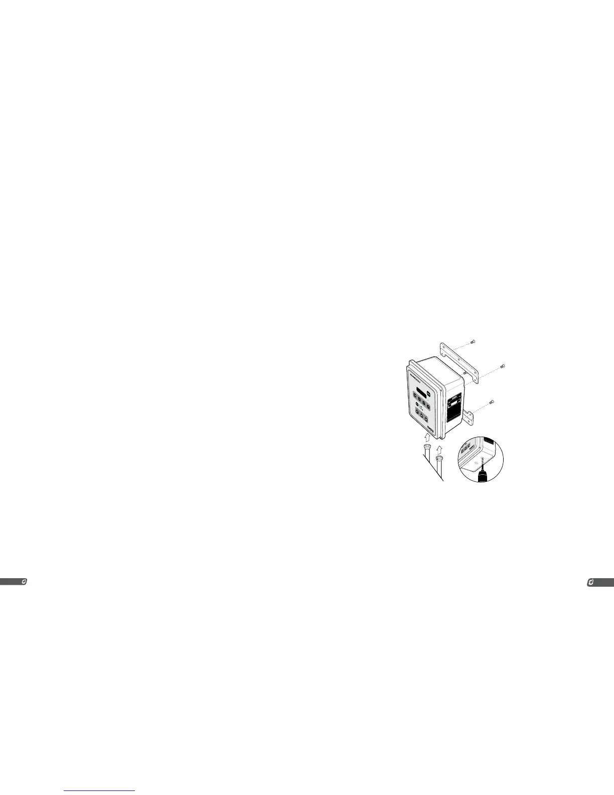
MOUNTING INSTRUCTIONS
1. Remove the included bag of components taped to the
mounting brackets.
2. Attach the two mounting brackets to the back of the PF2100
enclosure using the 4 provided screws.
3. Determine the best location to drill holes in the product
enclosure for the wires to enter. It is recommended that these
holes be drilled on the bottom of the enclosure (as shown).
4. Install grommets or conduit ports as required.