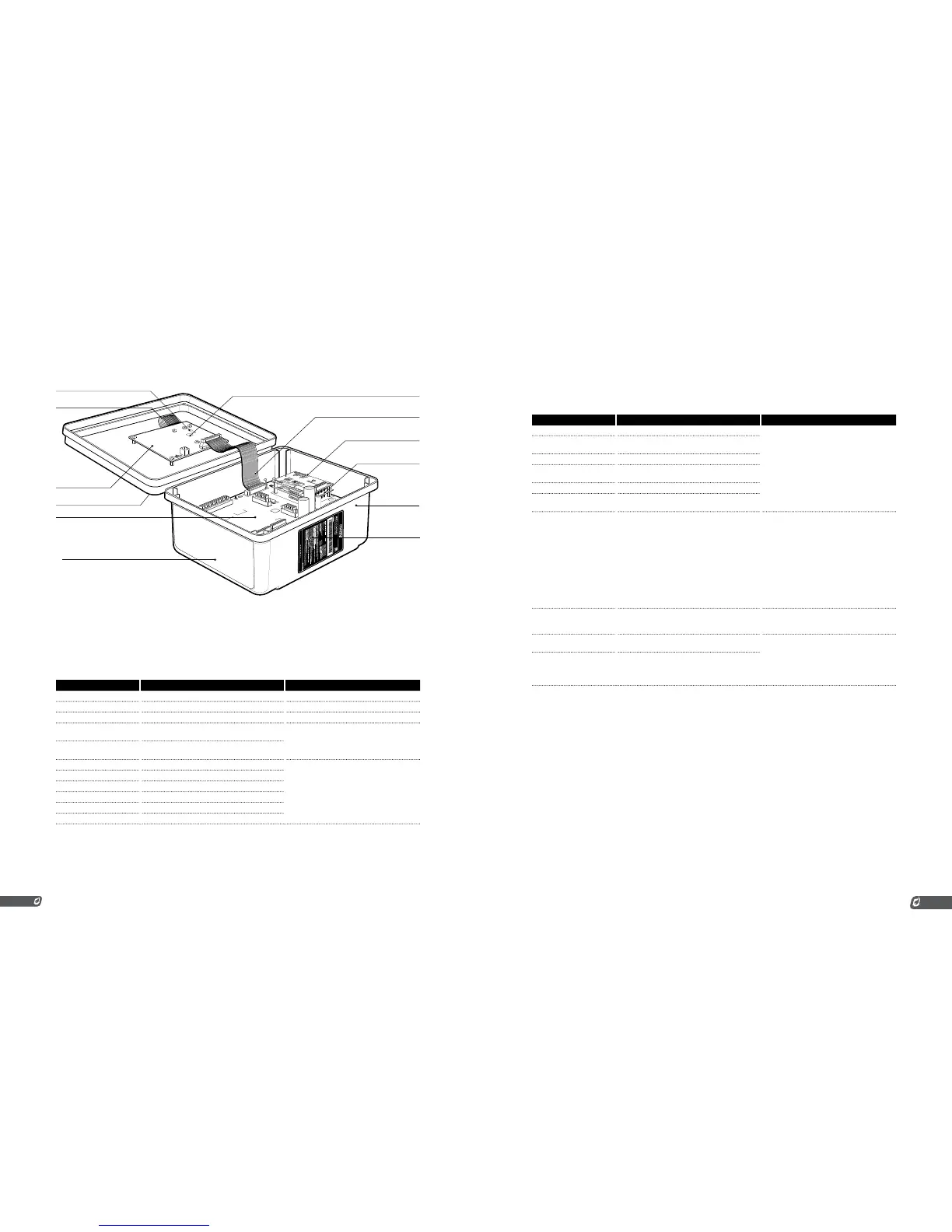
4-20mA REPEATER CARD
INTERNAL COIL
MODBUS or DATALOGGING CARD
RIBBON CABLE
FW VERSION LABEL
KEYPAD FLEX CABLE
HW SERIAL / VERSION LABEL
TERMINAL CARD
DOOR CARD
(optional)
(optional)
(optional)
DOOR & KEYPAD
SERIAL / MODEL LABEL
ENCLOSURE
1.8 | Terminal Card Descriptions
This table provides connection details and a brief description of each terminal.
TERMINAL EXPECTED CONNECTIONS DESCRIPTION
12/24VDC Input power from a DC source Input power 10VDC - 28VDC, 5A MAX
Common Ground back to DC source Internally connected to EGND
EGND Earth Ground
4-20mA Out + Proportional Valve positive terminal or PLC
4-20mA positive input
This output can be used for either Proportional
Valve Control or echoing the Process
Temperature to a PLC.
A resistance of 120Ω to 250Ω is expected.
4-20mA Out - Ground return for the 4-20mA output
HighTemp_TC + (YELLOW) High Temp Thermocouple positive lead
“TYPE K” thermocouple must be connected
between the “+” and “-” terminals and must
not be electrically connected to ground.
An uninterrupted connection using “TYPE K”
thermocouple wire is required for an accurate
reading.
HighTemp_TC - (RED) High Temp Thermocouple negative lead
Process_TC + (YELLOW) Process Thermocouple positive lead
Process_TC - (RED) Process Thermocouple negative lead
AUX_TC + (YELLOW) Aux Thermocouple positive lead
AUX_TC - (RED) Aux Thermocouple negative lead
TERMINAL EXPECTED CONNECTIONS DESCRIPTION
High Fire/Main + High Fire / Main Valve positive terminal
Solenoid valves must be connected between
the “+” and “-” terminals. The negative
terminal is not directly connected to ground so
a common return wire for the High Fire, Low
Fire and Pilot valves cannot be used.
Maximum continuous current is 2A. If Low
Power mode is enabled, a peak load of 4A is
permitted.
High Fire/Main - High Fire / Main Valve negative terminal. Do not
connect to ground.
Low Fire + Low Fire Valve positive terminal
Low Fire - Low Fire Valve negative terminal. Do not connect
to ground.
Pilot + Pilot Valve positve terminal
Pilot - Pilot Valve negative terminal. Do not connect to
ground.
Ion + Flame Detection positive input. Connect to flame
rod or external coil Ion terminal (depending on
configuration)
A Kanthal rod should be placed directly in
the pilot flame and connected to this input.
The pilot assembly must be grounded for the
flame detection to function properly. Input
is protected from high voltage and can be
connected in series with the high voltage
terminals of an external ignition coil, allowing
a single flame rod to be used for both ignition
and flame detection.
A 65VAC signal is applied to the flame rod. The
source impedance is very high so there is no
danger of sparking.
Ion - Flame Detection negative input. Connect to
ground screw on pilot assembly or burner
housing.
Ground return for flame detection.
Coil + Driver for the low voltage primary of the ignition
coil.
The primary of the ignition coil should be
connected to this terminal. The 12/24VDC
input power will be applied for 1 ms and
turned off for 50 ms while sparking.
This output is protected by a 250mA thermal
fuse.
Coil - Ground return for the ignition coil.