8584
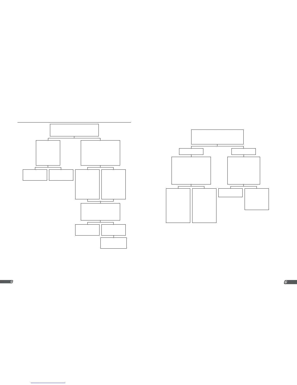
Flow Chart 2
Set the Multimeter to measure DC voltage across
ION + and ION - with the system in manual mode.
Is the reading across ION + and ION - around +5VDC?
Remove the wire from
ION + and measure
the DC voltage be-
tween the ION + and
ION - terminals again.
Is the voltage across the
ION + and ION - termi-
nals around +5VDC?
Put the system into Auto Mode and
monitor the voltage on the Multi-
meter. While sparking the voltage
will jump around; ignore this.
Take note of the voltage after the spark-
ing while the flame is still present.
Did the voltage drop below +5V when the
flame was present?
Check the ION + wire
for nicks or other faults.
It is possible that the
terminal card is faulty.
The system is not
seeing the flame at all.
The circuit from the rod
through the flame to
the nozzle to ground is
not being completed.
Check the grounding
to the pilot nozzle.
Check for cracked ce-
ramic on the flame rod.
The system is sensing
flame, just not enough.
The DC voltage should
drop to -5VDC or lower
(-8VDC is better for
stable flame detection.
Adjust the flame rod
positioning to try to de-
crease the voltage while
the flame is present.
The problem could be related to
flame anchoring. To verify this, place
a grounded rod in the flame.
Did placing the grounded rod in the flame
improve the DC voltage reading?
Recheck the orifice size
and increase the pilot
pressure.
Try replacing the pilot
nozzle.
Set the system up to use
separate rods for flame
detection and ignition.
6.6 | Thermocouple Troubleshooting Guide
Problem with Thermocouples.
Make sure that both the High Temp and Pro-
cess thermocouples are connected.
Is the system reading Process TC, ProcTC, HH thermo-
couple or ProcHTC?
Ye s
No
Likely TC’s not equal or TC mismatch.
Set a Multimeter to read millivolts DC
(mVDC) and measure across High-
Temp_TC + and HighTemp_TC -.
Also measure across Process_TC -.
Are the voltages measured across the
two thermocouples within 0.1 mVDC?
Check the thermocouple wir-
ing and make sure that the
thermocouples are paired
correctly (not reversed).
The thermocouple indication
by the system may be faulty.
Install a jumper across Pro-
cess_TC + and Process_TC -.
Did the error clear?
The system is likely
reading correctly. Set the
meter to read conti-
nuity and check that
the thermocouples are
paired correctly and not
reversed. If the thermo-
couples are paired cor-
rectly and not reversed
it is possible that one
of the thermocouples is
faulty and will need to be
replaced.
The system is likely out
of calibration. Recali-
brate the HighTemp_TC
and Process_TC.
If the calibration did not
resolve the problem, it is
possible that one of the
circuit boards will need
to be replaced.
One of the circuit boards
may be faulty.
There is likely a problem
with the thermocou-
ple or the wiring.
Verify that there is con-
tinuity between the red
and yellow wires for each
thermocouple.