1312
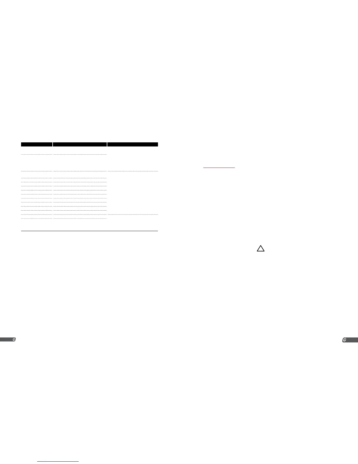
TERMINAL EXPECTED CONNECTIONS DESCRIPTION
Status + Connect to PLC positive input contact or other
alarm device.
The status “+” and “-” contacts will be closed
when the system is running and opened when
the system is shutdown. Dry contact output to
indicate system status to an external device.
ie. PLC. Note that the contacts are DC only
and are not internally connected to power or
ground.
40VDC, 250mA, 15Ω
Status - Connect to PLC negative input contact or other
alarm device.
Start + Remote start input from an external device. ie.
PLC.
Dry contact switch is expected. The input
is internally pulled up to 9VDC via a 3.75kΩ
resistance. Jumper “+” and “-” if not used.
All input contacts can use a single common
ground return if desired.
Start - Ground
ESD + External Shutdown input, typically plant ESD loop.
ESD - Ground
Proof of Closure + Proof of Closure from main valve(s).
Proof of Closure - Ground
High Pressure + Input from a mechanical High Pressure switch.
High Pressure - Ground
Low Pressure + Input from a mechanical Low Pressure switch.
Low Pressure - Ground
Level + Input from a float-switch mounted in the bath.
Dry contact switch is expected. The input
is internally pulled up to 9VDC via a 3.75kΩ
resistance. Jumper “+” and “-” if not used.
All input contacts can use a single common
ground return if desired.
Level - Ground
2 | INSTALLATION
The PF2100 can be used with many different systems. Before you begin installation, identify which
system the BMS will be used to control. In addition to this document, Profire has an Installation Guide
and several installation specific Whitepapers available describing common scenarios. These can be found
at www.profireenergy.com.
The steps provided here are general and can help you to identify questions that need to be answered to
complete the installation process. If you are new to the PF2100, you should read this whole section and
follow the instructions closely.
Steps
1. Review all installation warnings
2. Install the system
3. Connect the required wiring including Power, Valves,
Thermocouples, and Ignition Coil / Flame Detection wiring
4. Connect any additional wiring as required for your specific
application. Commonly used lines include the Status Contact,
Dry Contact Inputs, 4-20mA Temperature Output, and
Expansion Cards
To know which options are required, you should consult the engineer or technician who designed the
site. You should also be familiar with the local electrical and gas code for the site.
2.1 | Installation Warnings
!
Before installing the PF2100, please review the following list of warnings. Failure to consider these
warnings may result in death, electrocution, property damage, product damage, and/or government fines.
1. The PF2100 is not intended for use on burners greater than
12.5 MMBtuh. It is against code in many locations.
2. To use the PF2100 on burners greater than 5 MMBtuh, it is
recommended that the low fire feature with two safety shutoff
valves be used. At least one of these valves should use Proof
of Closure. This is required in many locations.
3. Failure to properly ground the pilot assembly back to the
PF2100’s Ion terminal may result in accidental electrocution,
product damage, or simply failure to ignite the pilot.
4. The PF2100 generates 20kV - 40kV at its high voltage output
terminal which can cause cardiac arrest. Do not touch or
place any object near the ignition coil’s high voltage terminal
or connected ignition wire while the product is operating.
Even without making physical contact with the terminal, it is
possible to draw a spark from several inches away, especially
if the pilot bracket is not properly grounded.
5. Never leave the PF2100 running unattended without the
door screws securely tightened down. This is to prevent
moisture from getting inside of the enclosure and damaging