5554
The system behaves the same as in the standard process control diagram until the demand for heat
drops.
1. The Process Temperature reaches the Process Setpoint and
the main valve closes.
2. The Process Temperature continues to rise.
3. The Process Temperature exceeds the Low Fire Setpoint, the
Low Fire Valve closes, and the Process Temperature drops.
4. The Process Temperature drops below the Process Setpoint
minus the Deadband, the High Fire Valve opens, and the
Process Temperature begins to increase again.
PROPORTIONAL VALVE CONTROL
The Low Fire: On Proc Setpoint can be used in conjunction with a proportional valve connected to the
4-20mA Output. In this mode, the PID Controller adjusts the proportional valve and attempts to fix the
temperature at the Process Setpoint.
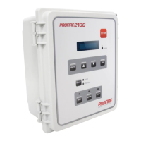
LOW FIRE: ON AT LOW FIRE SETPOINT
This example has the Low Fire feature enabled and set to “On at Low Fire Setpoint.” In this case, the Low
Fire Valve will close when it exceeds the Low Fire Setpoint, and will reopen after it drops below the Low
Fire Setpoint minus Deadband.
The system behaves the same as in the standard process control diagram until the demand for heat
drops.
TEMP DROPS BELOW
LOW FIRE SETPOINT
MINUS DEADBAND
122
TIME˚C ˚F
LOW FIRE SETPOINT
HIGH FIRE SETPOINT
DROPPED HEAT DEMAND
4
3
2
1
1. The Process Temperature continues to rise.
2. The Process Temperature exceeds the High Fire Setpoint, the
High Fire Valve closes, and the Process Temperature continues
to rise.
3. The Process Temperature exceeds the Low Fire Setpoint, the
Low Fire Valve closes, and the Process Temperature drops.
4. The Process Temperature drops below the Low Fire Setpoint
minus Deadband, the Low Fire Valve opens, and the Process
Temperature begins to rise again.
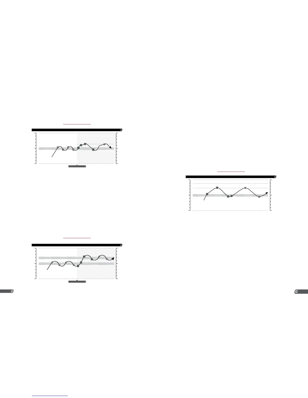
PILOT OFF
This scenario is the same as the basic scenario except that the Pilot Off feature has now been enabled.
In this case, when the Proc Temp rises above the Pilot Off Setpoint the Pilot Valve will close and will not
re-light until the temperature is below the Process Setpoint minus Deadband.
The system behaves the same as in the standard process control diagram with the added ability to shut
off the pilot as needed.
1. The temperature exceeds the Proc Setpoint and the Main
Valve closes.
2. The temperature continues to rise and the Proc Temp exceeds
the Pilot Off Setpoint, the Pilot Valve closes, and the Proc
Temp begins to decrease.
3. The Proc Temp drops below the Process Setpoint minus
Deadband, the pilot relights, and the Proc Temp begins to
increase again.
4. The Pilot-to-Main Delay elapses, the Main Valve opens, and
the Proc Temp begins to increase faster.
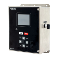
HIGH TEMP ESD
The High Temp ESD Setpoint is always compared against the High Temp Thermocouple regardless of
the Process Control setting. The system will immediately shut down if this thermocouple exceeds this
setpoint. Because the High Temp Thermocouple and Process Thermocouple must always be in the same
thermowell, these two thermocouples can be thought of as being the same. Note that the internal signal
to which the Process Thermocouple is associated (Proc Temp or Aux Temp) will change depending on the
Process Control setting.
This particular graph is a representation of a high temperature shutdown. Once the Process Temperature
exceeds the High Temp ESD Setpoint, the system will shut down and require user input to acknowledge
the error.