ALARM
(NO
CONTACT)
OPEN
CLOSED
OPEN
2 4 5 6
7
31
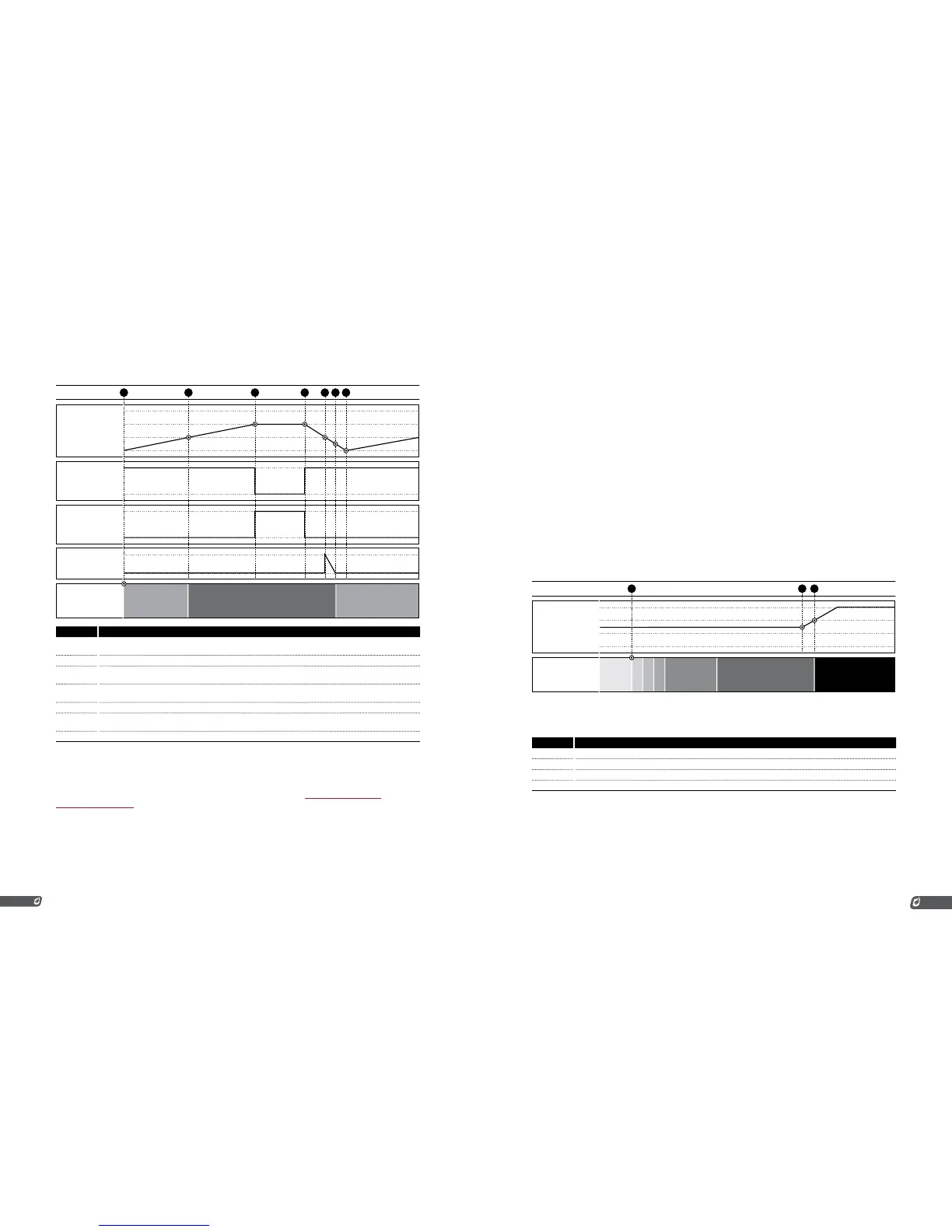
# CHART 1 EVENTS
1 System started with tank empty. Pump starts filling tank. Burner is off and system is waiting on level input
because 4-20mA level input is below the low setpoint.
2 Tank level rises above low setpoint. System begins running (heating tank).
3 Tank level rises above the high setpoint, the pump turns off and the remote alarm turns on to signal a truck to
come and empty the tank.
4 An operator arrives on site and begins emptying the tank into a tanker truck. The pump turns back on and the
alarm turns off.
5 The tank level drops below the low setpoint and the level delay timer begins counting down.
6 The level delay timer reaches zero after 2 or 20s (depending on the “Pressure/Level Delay” setting) and the
system stops heating the tank and returns to the “Waiting on Level” state.
7 The tank is empty and the tanker truck leaves the site. The tank level begins rising again.
4-20MA PRESSURE INPUT
The 4-20 Pressure Input is used to monitor fuel train pressure in the same way as the Pressure Contacts.
The behavior and features are similar to those described in the previous Low Pressure Contact and
High Pressure Contact sections. One difference is that a Pressure Transmitter is used instead of a pair
of Pressure Switches and the setpoints are set via a menu instead of mechanically on the switches.
When the 4-20 signal is below the low setpoint or above the high setpoint, the system will stop. When
it is between the two setpoints, it will run. The system can be started when the input signal is above the
high pressure setpoint. This is to allow for easy recovery from the common issue of leaky regulators.
If the regulator upstream from the high pressure switch is leaky, it can allow pressure to accumulate
at the switch’s position over time while the system is not running. Since there is no way to relieve this
pressure other than to open a downstream valve, the system must be allowed to start running under this
condition. The system will start, light the pilot, and open the main valve to allow the built-up pressure to
be relieved. If the pressure does not drop below the high pressure setpoint within 2 seconds after the
main valve has been opened, the system will shutdown. Otherwise it will continue running. This behavior
is depicted in charts 2 and 3 below. The system can be setup to restart from a low pressure event but not
from a high pressure event.
To use the 4-20 Pressure Input, it must be setup as follows:
1. Attach a properly calibrated Pressure Transmitter to the 4-20
Pressure Input
2. Enable the Pressure DIP Switch on the 4-20 Card
3. Enable the 4-20 Card in menu 6
4. Set the Pressure Low Setpoint, High Setpoint, Range, and
Units in menu 6
5. Disable the Low Pressure and High Pressure Contacts by
installing a jumper in each of them
Chart 1: Pressure Increases While Running
SYSTEM
STATE
READY
PURGE
IGNITE
FLAME
MAINPILOT DELAY SHUTDOWN
4-20 PRESSURE
20mA
4mA
EVENT
2 31