Typical Prolon Wiring Schematics
1
4
3
2
COM
24VAC
INT -
INT +
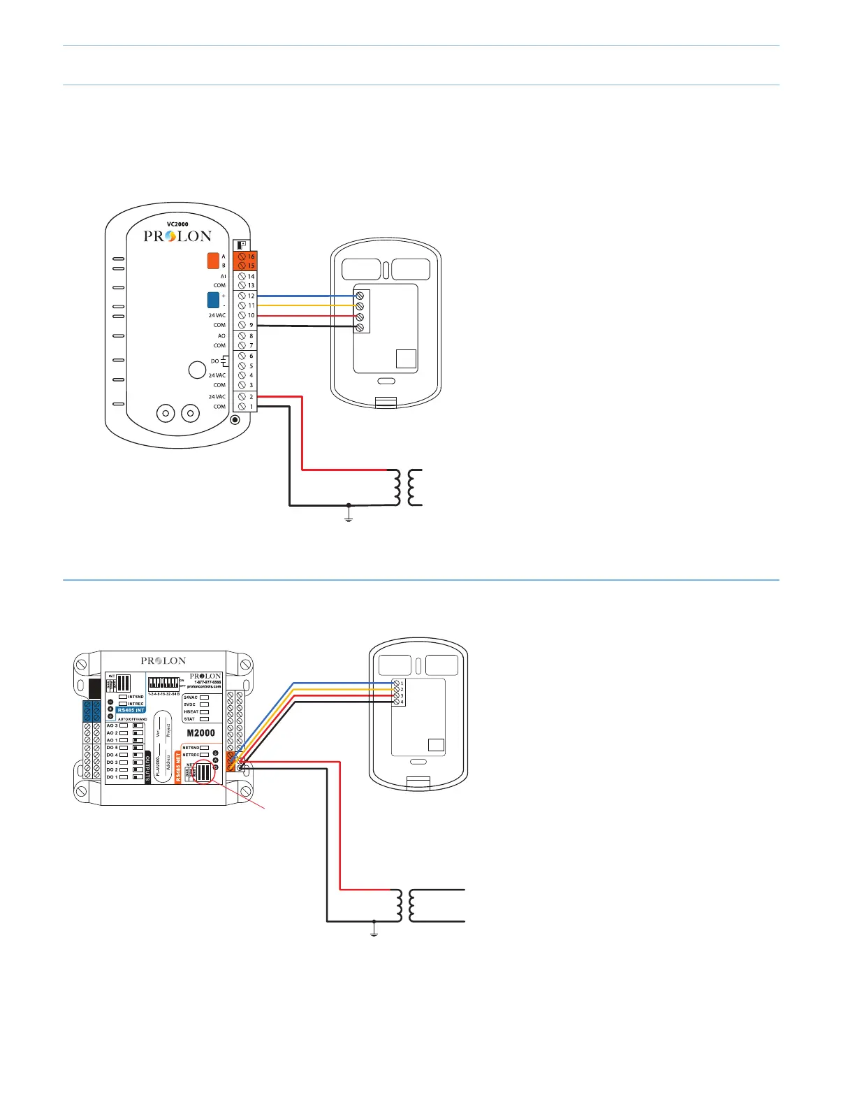
ProLon Communication and Power Supply (24 VAC) Wiring :
Zone controller and Digital Sensor
DIGITAL WALL SENSOR
PL-T1000/PL-T500/PL-T20
0
Recommended wiring for communication: #24/2, stranded, twisted and shielded, low-capacitance.
Recommended wiring for 24vac supply: #18/2, stranded
24 VAC Transformer
PL-VC2000(-PI)
ZONE CONTROLLER
RS485
NET
RS485
INT
12345678
BIAS ON
TERMINAL ON
BIAS ON
PL-M2000-RTUS or PL-M2000-HPS
SINGLE ZONE UNIT CONTROLLER
DIGITAL WALL SENSOR
PL-T1000/PL-T500/PL-T200
COM
24VAC
INT -
INT +
24 VAC Transformer
-or-
R&C Terminals from Unit
PL-VC2000 Zone Controller +
Digital Wall Sensor
•Recommended wiring for communication:
#22/2, stranded, twisted and shielded, low-
capacitance.
•Recommended wiring for 24vac supply:
#18/2, stranded.
PL-M2000 Single-Zone Unit
Controller + Digital Wall Sensor
•Recommended wiring for communication:
#22/2, stranded, twisted and shielded, low-
capacitance.
•Recommended wiring for 24vac supply:
#18/2, stranded.
*Connect “24VAC“ and “C” terminals to “R”
and “C” terminals respectively on A/C
control board.
3-4
 Loading...