Before powering up any Prolon control system for the rst time, a safety check list should be performed on all devices,
their wiring, and connections. This will ensure a successful start-up. (Consult: Installation Checklist PL-INSTL-
CHECKLIST-EN document for complete details).
Although not exhaustive, that list should include:
• Checking the power supply source
• Shielding and grounding of appropriate cables
• Addressing the controllers
• Setting up Termination / Bias resistors where needed
• Powering up and checking indicator light behavior
Power Supply Source
Supply to controllers must be 24VAC +/- 10%. The transformers used must have their common tab grounded to earth. All
controllers must share same the same 24vac Live -vs- Neutral terminal connections, as incorrect supply voltage polarity may
not cause damage but will cause communication failure until corrected.
Addressing Controllers
All controllers must have a valid address (anywhere from #1 to #127) to be able to communicate on a network. Even if left
standalone, zone controllers (C1050, VC2000) must still have an address to communicate with their own digital wall sensor.
•C1050 & M2000 controllers use dipswitches to set their address. They have no default addresses
•NC2000 Network Controller uses virtual addressing. It has factory set default address: #99
•T1100 Thermostat uses virtual addressing. It has factory set default address: #101
•VC2000 VAV controller uses virtual addressing. It has no default address
Terminating & Bias Resistors
Each communication segment of a networked system must have Terminating (end-of-line) as well as BIAS resistors enabled.
Checkthattheterminatingresistorjumpersareenabledonlyoneachofthetwooppositecontrollersonthecommunication
segment.Also,asinglecontrollermusthaveitsBIASresistorjumpersenabledaswell(Consultsection#4fordetails).
Grounding of Cables
Communicationbusshieldonanysegment(INT&NET)mustbegroundedatonlyoneendofthesegment,joinedbetweenall
networked controllers, and left isolated at the other end. (Consult PL-INSTL-WIRING-EN for complete details).
System Start-up
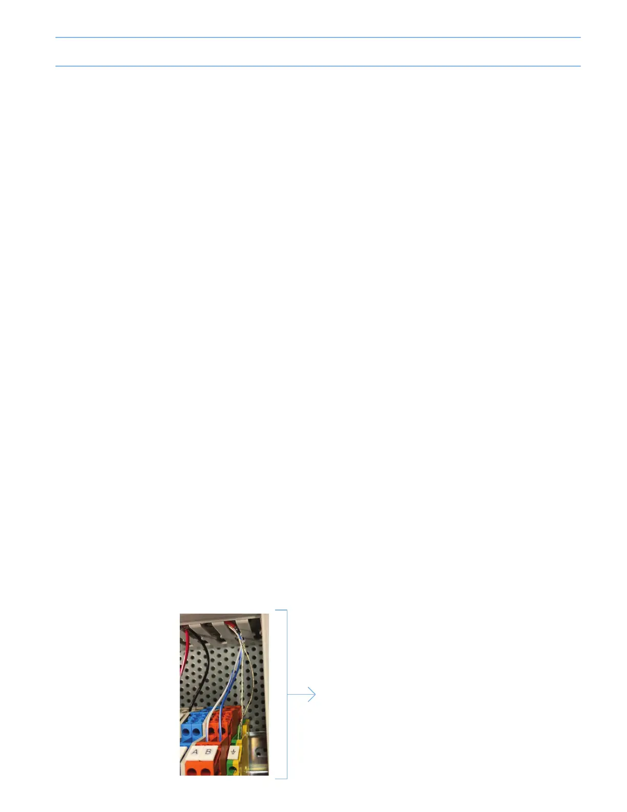
Shielded sensor wire, when
used, must only be grounded
at one extremity, typically at
the Master controller end.
5-5