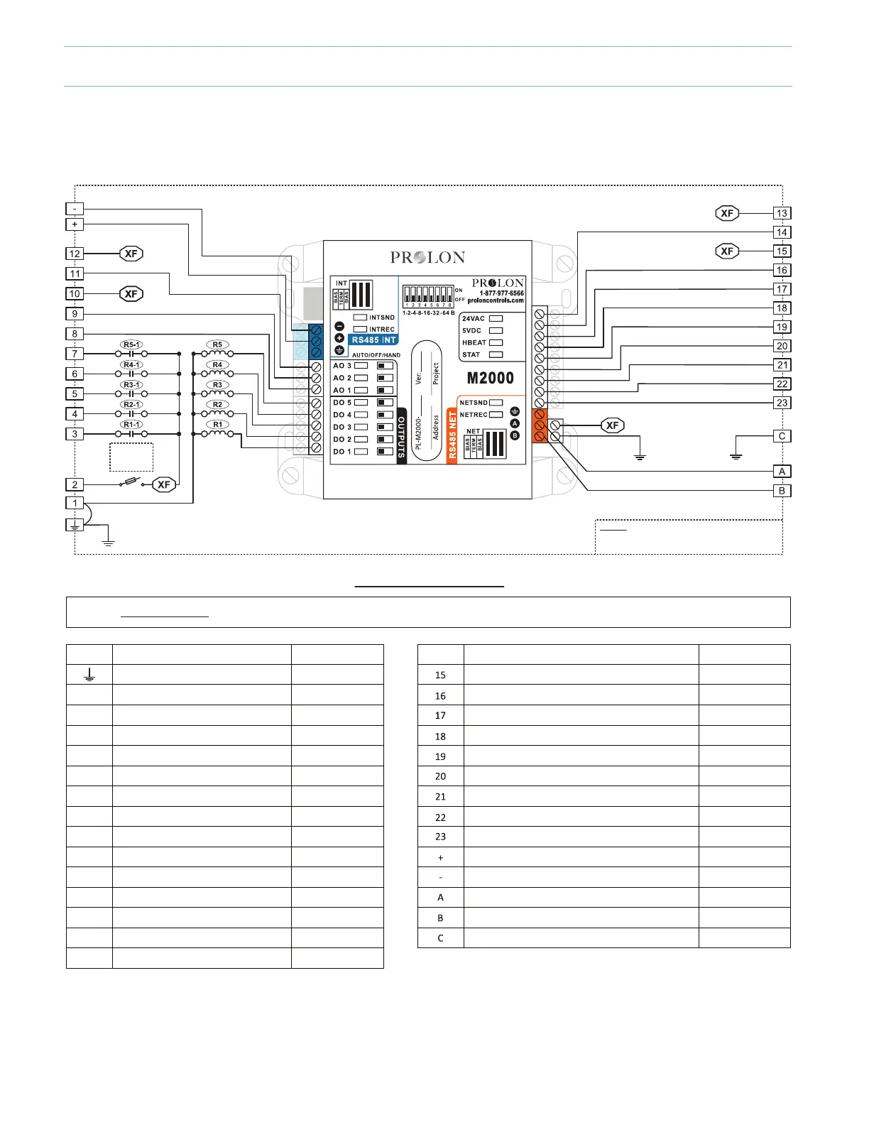
Panel Wiring Single M2000 (PL-PANEL-M2000-RTU)
Field Wiring Details
Internal Electrical Wiring Diagram
Legend
R1 - R2 - R3 - R4 - R5: Single pole, double throw relays
XF: Interconnection carrying 24VAC
3A 250V
Cartridge
Fuse
ALL TERMINALS: Use Copper Conductors Only, 105°C/220°F, Maximum Torque Conductor Mounng: 0.5Nm
CO2 Sensor Supply
CO2 Sensor Input Signal
Dry Contact for Proof of Fan
Zone Setpoint Potenometer (0-9K)
Zone Temperature Thermistor (10K Type 3)
Variable Funcon Temperature Sensor
Supply Air Temperature Thermistor (10K Type 3)
Return Air Temperature Thermistor (10K Type 3)
Outside Air Temperature Thermistor (10K Type 3)
M2000 RS485 INT A (+)
M2000 RS485 INT B (-)
M2000 RS485 NET A (+)
M2000 RS485 NET B (-)
COMMON
24VAC, 6.7VA
4-20mA, 1-5VDC
N/A
N/A
N/A
N/A
N/A
N/A
N/A
N/A
N/A
N/A
N/A
N/A
Terminal
RangsFunconTerminal
1
2
3
4
5
6
7
8
9
10
11
12
13
14
N/A
N/A
24VAC, 3A, 60Hz
24VAC, 300mA
24VAC, 300mA
24VAC, 300mA
24VAC, 300mA
24VAC, 300mA
0-10VDC, 40mA
0-10VDC, 40mA
24VAC, 8.5VA
0-10VDC, 40mA
24VAC, 5VA
24VAC, 0.03A
0-5VDC, 5uAStac Pressure Sensor Input Signal
Funcon Rangs
GROUND
Power Supply Input Common
Power Supply Input 24VAC
Fan Output (G)
Cooling Output 1 (Y1)
Cooling Output 2 (Y2)
Heang Output 1 (W1)
Heang Output 2 (W2) or Exhaust Fan
Modulang Heang Output
Economizer Control Output
Economizer Supply
Bypass or VFD Control Output
Bypass or VFD Supply
Stac Pressure Sensor Supply
4-24