PATHWAY
®
MR-20 OPERATOR’S GUIDE
18
CHAPTER 1: PHYSICAL/MECHANICAL OVERVIEW
Connecting Pathway
®
Electrode(s) to Pathway
®
Preamplier(s): The Pathway
®
Preampliers (Part #2583) have three female snap on electrode positions: two labeled
(ACT) for active electrodes and one (GND) for the ground electrode. Verify the male
tabs of the Pathway
®
Electrodes (Part #6750) are snapped into the corresponding
female snaps of the Pathway
®
Preamplier (Part #2583).
Skin Preparation: Prepare the skin with an alcohol pad to avoid high impedance
artifact. Wipe dry with a tissue or cloth.
Pathway
®
Electrode Preparation: With the Pathway
®
Electrode (Part #6750)
attached to the Pathway
®
Preamplier (Part #2583), use the white tab on the Pathway
®
Electrode (Part #6750), to carefully remove the mylar backing being cautious to keep
the hydrogel adhesive strips intact on the surface of the electrode.
Pathway
®
Electrode Placement: Place the two active (ACT) electrodes over the bulk
of the muscle. Make sure the length of the Pathway
®
Electrode (Part #6750) is placed
parallel with the muscle bers as shown in Figure 1 below.
Figure 3. Figure 4.
Cable Connections for Orthopedic: Connecting the Pathway
®
Preamplier(s) (Part #2583) to Pathway
®
Electrodes (Part #6750)
Example: Electrode Placements for VMO / VL Deciency
Back of Electrode
Hydrogel Strips
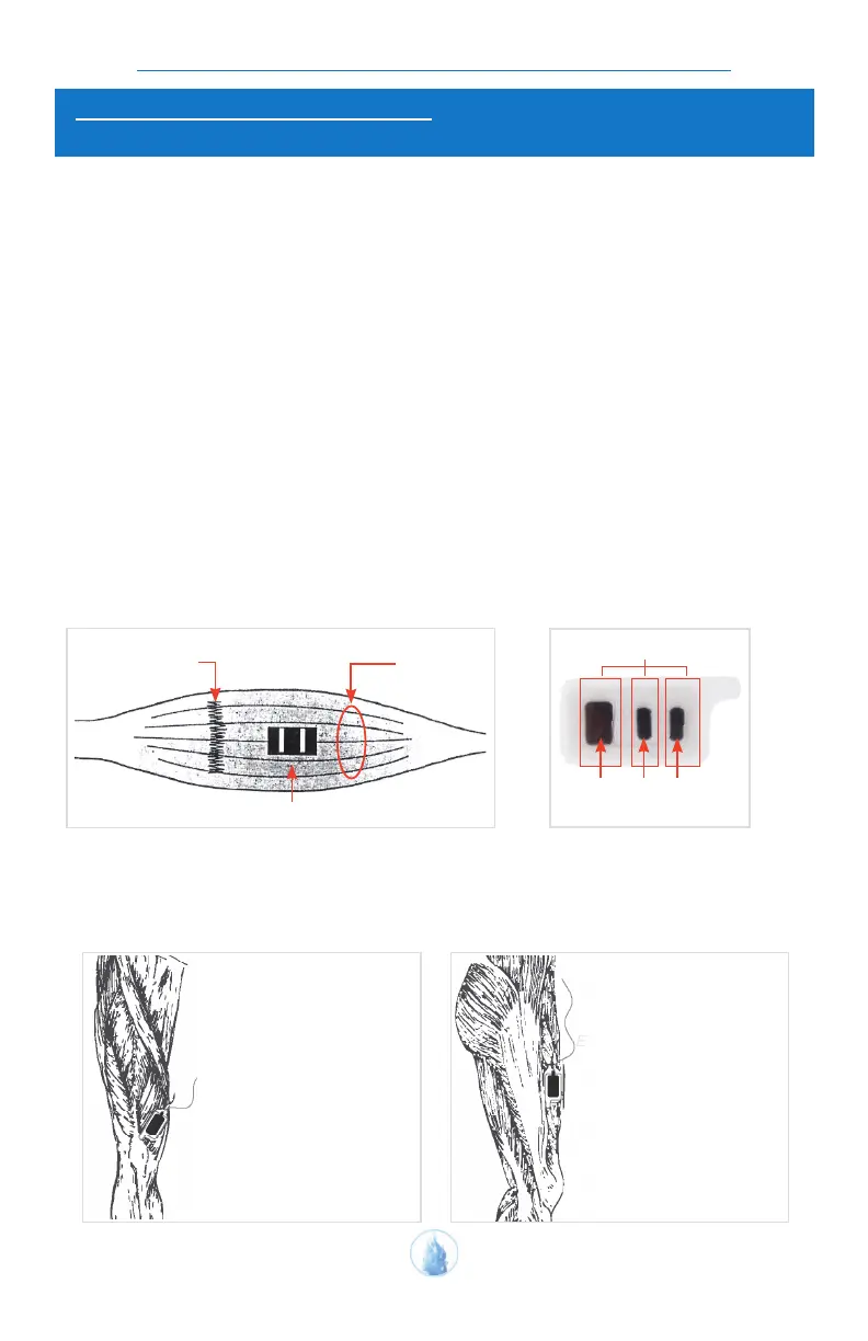
Figure 1. The preferred electrode location is between the
motor point (or innervation zone) and the tendinous insertion,
with the detection surfaces arranged so that they intersect as
many muscle bers as possible.
Tendinous insertion
Electrode
Muscle Fibers
GND ACT ACT
Sensing Surfaces of Pathway
®
Electrode (Part #6750)
Figure 2. Back of Pathway
®
Electrode (Part #6750) showing
placement of sensing surfaces
and adhesive gel strips.
EMG A Placement
The electrode for EMG A is placed
over the bulk of the VMO
(Vastus Medialis Oblique)
and runs parallel to
the muscle bers.
Leg - Head on view
(Primary Muscle)
EMG B Placement
The electrode for
EMG B is placed over the bulk
of the VL (Vastus Lateralis)
and runs parallel to the
muscle bers.
(Secondary Muscle)
Leg - Side prole view