If the HMI is mounted remotely from the pump: a clearly marked Stop
mechanism must be installed in the direct vicinity of the pump for emer‐
gencies!
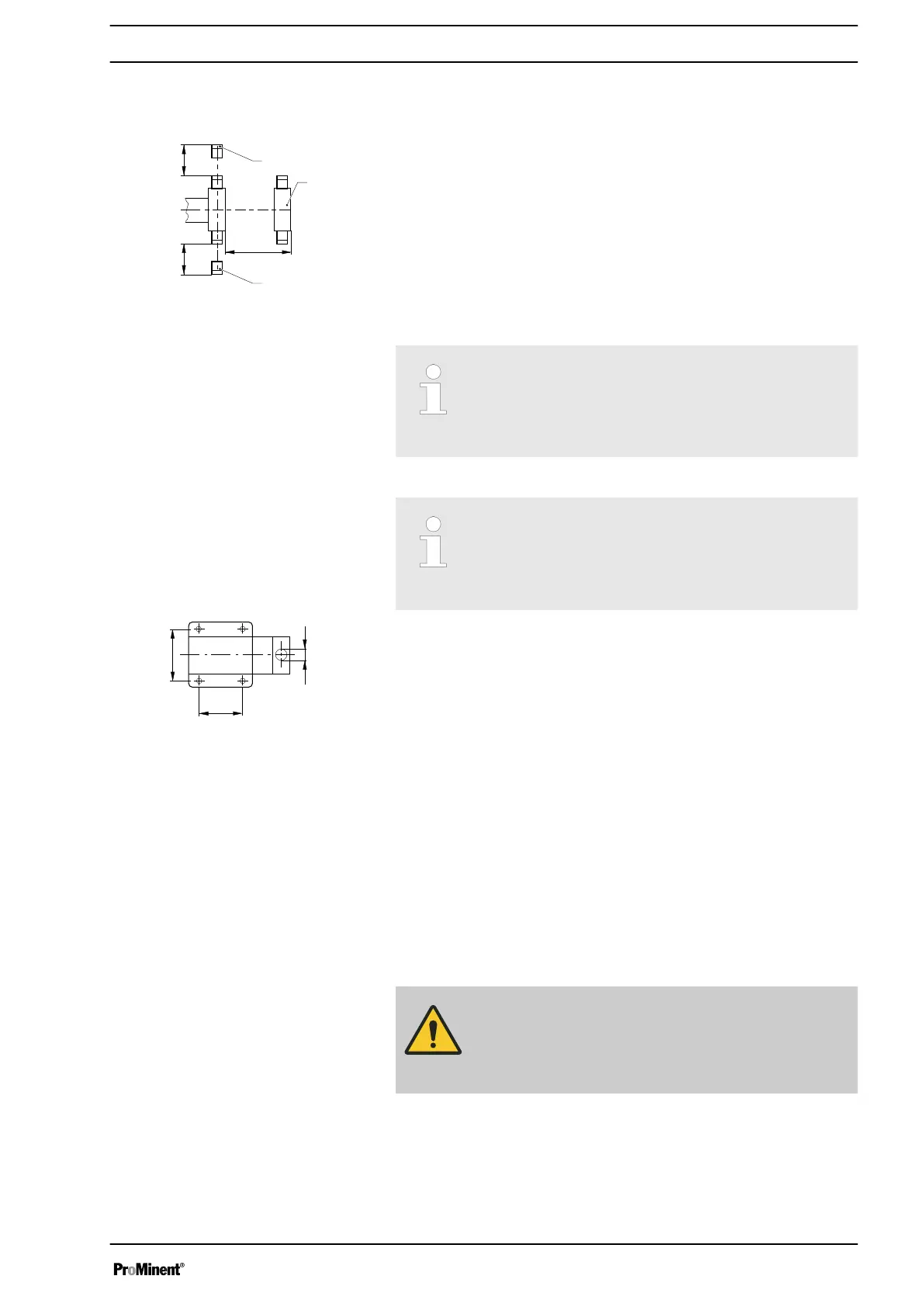
1 Discharge valve
2 Dosing head
3 Suction valve
Ensure there is sufficient free space (f) around the dosing head as well as
the suction and discharge valve so that maintenance and repair work can
be carried out on these components.
Capacity too low
The liquid end valves cannot close correctly if they are
not upright.
–
Ensure that the discharge valve is upright.
Capacity too low
Vibrations can disturb the liquid end valves.
–
Secure the metering pump so that no vibrations can
occur.
Take the dimensions (m) for the fastening holes from the appropriate
dimensions- or data sheets.
Use appropriate bolts to fix the pump base to the supporting floor.
Mounting the HMI user control
If ordered with the wall mounting, the HMI can be mounted directly on a
wall.
Install the HMI in the immediate vicinity of the pump. If not provided for, fit
a circuit breaker there - refer to the "Installation, electrical" chapter. Ensure
that the system is arranged ergonomically.
When doing so, consider the available cable length.
Prevent tripping hazards.
Refer to the relevant dimensional drawing for the dimensions of the HMI
and fixing holes.
CAUTION!
Warning of faulty operation
– Do not install the HMI and cable too close to devices
and cabling that emit strong electrical interference.
Fig. 12
Liquid end alignment
Fastening
Fig. 13
Assembly
25

 Loading...


