15 Technical data
15.1
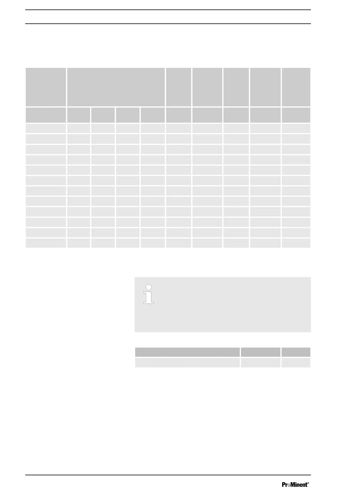
Performance data
Type Minimum pump capacity at maximum
back pressure
Max‐
imum
stroke
rate
Suction
lift
Permis‐
sible pri‐
ming pres‐
sure,
suction
side
Connector
size
bar psi l/h gph Strokes/
min
ml/stroke m WS bar R"-DN
16050 PVT 10 145 61 16 90 11.4 7 2 1" - 15
16050 SST 16 232 56 14 90 11.4 7 2 1" - 15
16090 PVT 10 145 109 28 160 11.4 7 2 1" - 15
16090 SST 16 232 99 26 160 11.4 7 2 1" - 15
16130 PVT 10 145 131 34 200 10.9 7 2 1" - 15
16130 SST 16 232 129 33 200 10.9 7 2 1" - 15
07120 PVT 7 102 150 39 90 27.4 5 1 1 1/ - 20*
07120 SST 7 102 150 39 90 27.4 5 1 1 1/ - 20*
07220 PVT 7 102 271 71 160 27.7 5 1 1 1/ - 20*
07220 SST 7 102 271 71 160 27.7 5 1 1 1/ - 20*
04350 PVT 4 58 353 93 200 29.4 5 1 1 1/ - 20*
04350 SST 4 58 353 93 200 29.4 5 1 1 1/ - 20*
All figures refer to water at 20 °C.
The suction lift applies to filled suction line and filled liquid end - when
installed correctly.
* For Sigma types 07120, 07220 and 04350 the valves in
the dosing head are of type DN 25 (G1 1/2). As for these
types of pipes, DN 20 is generally sufficient (see tech‐
nical data, suction/discharge side connector), the con‐
nector parts that can be ordered under the identity code
(e.g. inserts) are already reduced to DN 20, i.e. piping
and accessories can be installed in DN 20.
Data Value Unit
Reproducibility ±2 % *
* - when installed correctly, under constant conditions, at least 30%
stroke length and water at 20 °C
S2Cb
Precision
Technical data
86