CAUTION!
Danger due to incorrect use of the integral relief valve
The integral relief valve can only protect the motor and
the gear, and then only against impermissible positive
pressure that is caused by the metering pump itself. It
cannot protect the system against positive pressure.
– Protect the motor and gear of the system against
positive pressure using other mechanisms.
–
Protect the system against illegal positive pressure
using other mechanisms.
CAUTION!
Warning of feed chemical spraying around
If no overflow line is connected to the integral relief valve
or the integral bleeder valve, feed chemical will spray out
of the hose connector as soon as the relief valve opens.
– Always connect an overflow line to the integral relief
valve or the integral bleeder valve and feed it back
into the storage tank or - if required by the regula‐
tions - into a special storage tank.
CAUTION!
Danger of cracking
Cracking of the PVT liquid end can occur if a metal over‐
flow line is connected to the relief valve.
– Never connect a metal overflow line to the relief
valve.
CAUTION!
Danger of the integral relief valve failing
The integral relief valve no longer operates reliably with
feed chemicals having a viscosity of greater than 200
mPa s.
– Only use the integral relief valve with feed chemicals
having a viscosity up to 200 mPa s.
CAUTION!
Warning against leaks
Feed chemical, which remains in the overflow line at the
relief valve or bleeder valve, can attack the valve or
cause it to leak
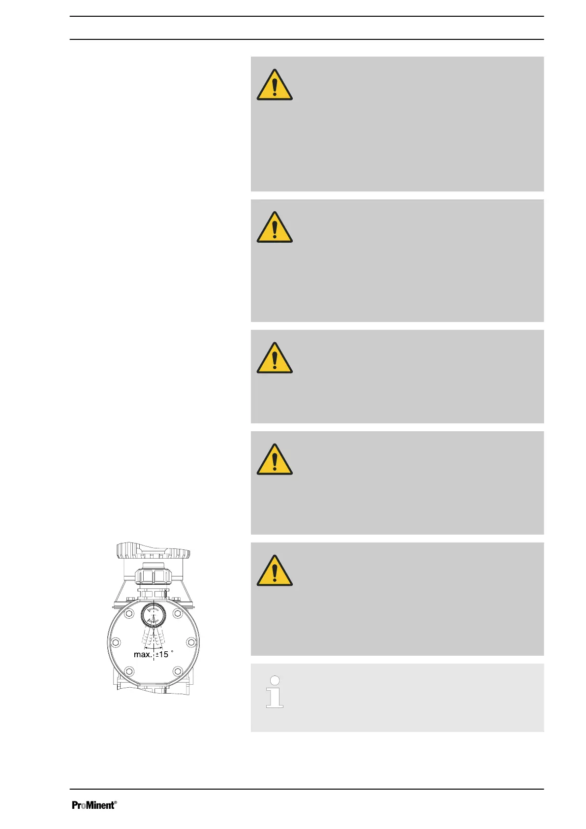
– Route the overflow line with a continuous slope and
moreover with the tube nozzle pointed downwards -
see .
If the overflow line is fed into the suction line, the bleed
function is blocked.
Therefore lead the overflow line back into the storage
tank.
Fig. 18: Permissible alignment of the relief
valve
Installation
29

 Loading...


