Measuring Signal Performance
Edge
TM
Multipoint and Quickbridge - Hardware Installation Guide 62
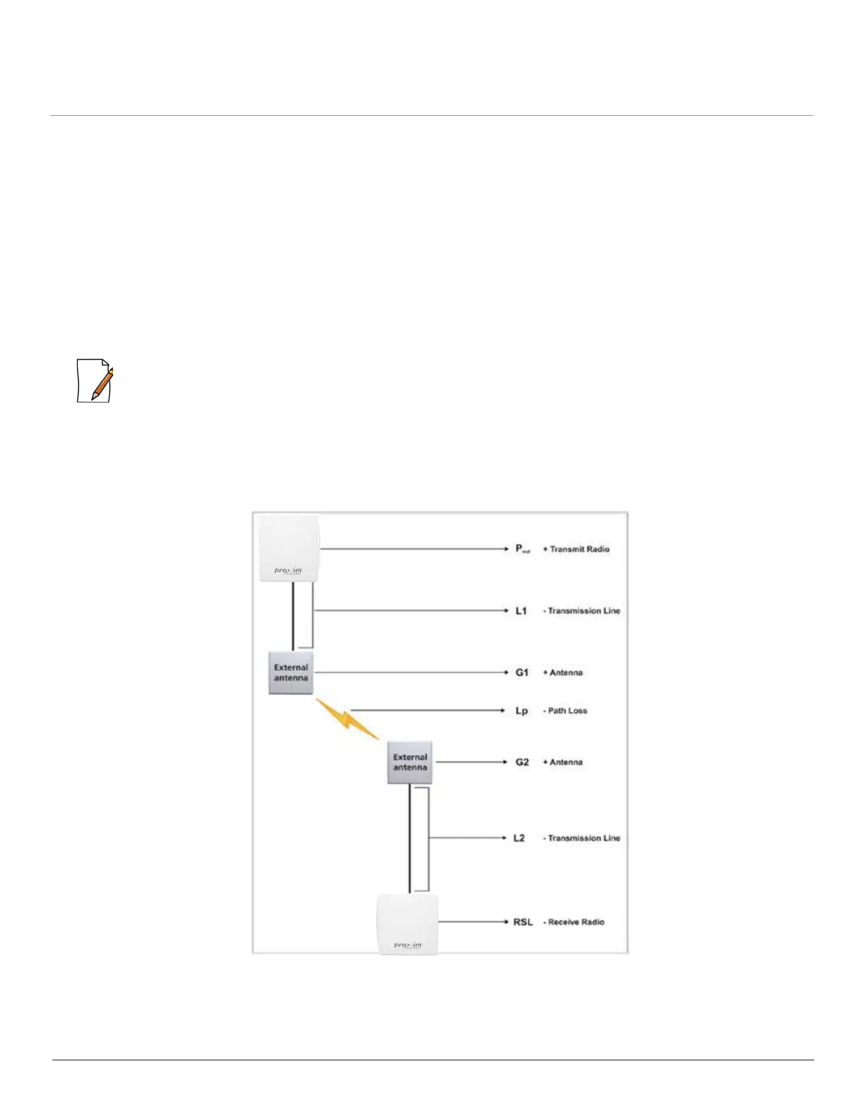
where:
• P
out
is the output power (in dBm) of the transmitter.
• L
1
is the total loss of all transmission elements between the antenna and the RF device on one side of the link (in dB).
• G
1
is the gain of the antenna on one side of the link (in dB).
• G
2
is the gain of the antenna on the opposite side of the link (in dB).
• L
2
is the total loss of all transmission elements between the antenna and the RF device on the opposite side of the link (in
dB).
• L
p
is the Path loss, defined by:
Lp (dB) = 96.6 + 20 log
10
F + 20 log
10
D; where:
– F is the frequency of the radio system in GHz.
– D is the distance of the path in miles.
:
• This formula is available on a calculation sheet provided by Proxim to generate an estimate of link distance and
reliability.
• The path loss must be smaller than the link budget minus the minimum required fade margin. The maximum ranges
cause the path loss plus the fade margin to be the same as the link budget.
The following figure is a pictorial representation of the elements in the Link Budget equation.
Figure 9-4 Link Budget Equation-Pictorial Representation
 Loading...