PS Engineering
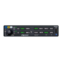
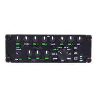
PMA8000G IntelliAudio Audio Selector Panel With flightmate®
Installation and Operator’s Manual
200-890-0912 Appendix E Rev. 7, July 2017
Appendix E – Instructions for FAA Form 337 and continuing air-
worthiness
8.1 Instructions for FAA Form 337, Audio Panels
One method of airworthiness approval is through an FAA Form 337, Major Repair and Alteration (Airframe, Powerplant, Pro-
peller, or Appliance) In the case of the PMA8000G, you may use the following text as a guide.
Installed audio selector and 6-place intercom, PS Engineering PMA8000G, part number 050-890-(XXXX) in ( location )
at station . Installed per AC43.13-2, Chapter 2, paragraph 23 (Instrument Panel Mounting). Installed per PS En-
gineering Installation Operators Manual p/n 200-890-(XXXX), revision (), dated ( ).
These units are FAA-Approved under TSO C50c for audio amplifiers, and/or TSO C35d for Marker Beacon Receivers,
TSO C71 for DC to DC power converters, and meets appropriate environmental qualifications outlined in RTCA DO-
160D as appropriate or this aircraft.
Interface to existing aircraft radios in accordance with installation manual and in compliance with practices listed in
AC43.13-2, Chapter 2. All wires are Mil-Spec 22759 or 27500. Connection to aircraft dimmer bus is
____________________. Power is supplied to the unit through a 3A circuit breaker (type and part number), and total
electrical load does not exceed % of the electrical system capacity with the PMA8000G added.
Aircraft equipment list, weights and balance amended. Compass compensation checked. A copy of the operation instruc-
tions, contained in PS Engineering document 202-890-( ), revision ( ), dated ( ), is placed in the aircraft records. All work
accomplished listed on Work Order .
8.2 Instructions for Continuing Airworthiness, Audio System
Sample ICA Checklist for PS Engineering Audio System:
In the event of a unit problem, place the unit into “off,” “fail-safe” and/or
“emergency” mode. This allows pilot communications using COM 1. Follow
checkout instructions in the installation manual referenced on the FAA Form
337. For a specific unit fault, contact the manufacturer at (865) 988-9800 for
special instructions.
Removal: Using a 3/32” Allen-head wrench, carefully unscrew the locking
screw located in the center of the unit. While turning the wrench CCW, gently
pull on the EDGES of the bezel until the unit is free from the mounting tray.
Installation: Engage the locking screw at the back. Turn the locking screw CW,
while applying slight pressure to the edges of the bezel. Do not over tighten!