PS Engineering
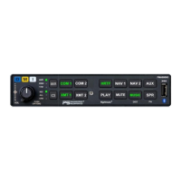
PMA8000G IntelliAudio Audio Selector Panel With flightmate®
Installation and Operator’s Manual
200-890-0912 Page 2-6 Rev. 7, July 2017
2.4.12 Public Address Mode
By pressing SPR pushbutton for more than 1 second, the PMA8000G will be placed into public address
(PA) mode. SPR light will flash letting the pilot know PA Mode is active. In this mode, the pilot will be
talking over the cockpit speaker when he presses his PTT switch. Copilot will still continue on the selected
COM radio.
2.4.13 PA Mute (J2, Pin 12)
Pin 12 of J2 is a TTL logic output that is active low during PTT operation.
2.4.14 Miscellaneous Logic Output (J2, Pin 18)
Pin 18 of the J2 connector is pulled to ground whenever the AUX button is depressed. This serves as a con-
trol line for external devices, such as an entertainment system that the pilot wishes to control.
This pin can also be used to control passenger (Music 2) Karaoke Mode, by connecting to pin 13 of the J2.
NOTE
J2, Pin 18 should NOT be used if the AUX is going to be used to switch ADF, DME or auxiliary audio.
2.4.15 CVR Output (J2, Pin 29) (Serial Number F1256 and above only)
The CVR output contains the audio as heard by the pilot, including selected radios, sidetone, and intercom
audio. CVR Audio low can be connected to any convenient audio low such as J2-34.
2.5 flightmate® connections
The flightmate® is an audio storage system with three features, radio playback, stored audio playback for a
checklist or reminders, and four audio messages can be triggered by external triggers, and acknowledged if
desired.
2.5.1 Message triggers:
NOTE:
THESE MESSAGES ARE STRICTLY SUPPLEMENTAL AND PILOT OPTION, AND
SHALL NOT REPLACE ANY EXISTING ALERTS IN THE AIRCRAFT.
Alert #1 is configured to accept an active high, but shall cease to play when the stimulus is removed. This
is intended for such a system as a stall warning, which clears autonomously, or will stop with the acknowl-
edgement.
The messages are stopped with the momentary push of the PLAY button, or an external Acknowledge but-
ton. When J1-28 is grounded through a NO Momentary switch as an ACK button, the messages will stop
playing. If J1-28 is connected to ground permanently, the message will play once when triggered and then
stop.
NOTE: Some GMA340 inputs pins may have been used in previous installations and will have to be repur-
posed or removed if no longer needed.
These are: