PS Engineering
PMA8000G IntelliAudio Audio Selector Panel With flightmate®
Installation and Operator’s Manual
200-890-0912 Rev. 7, July 2017
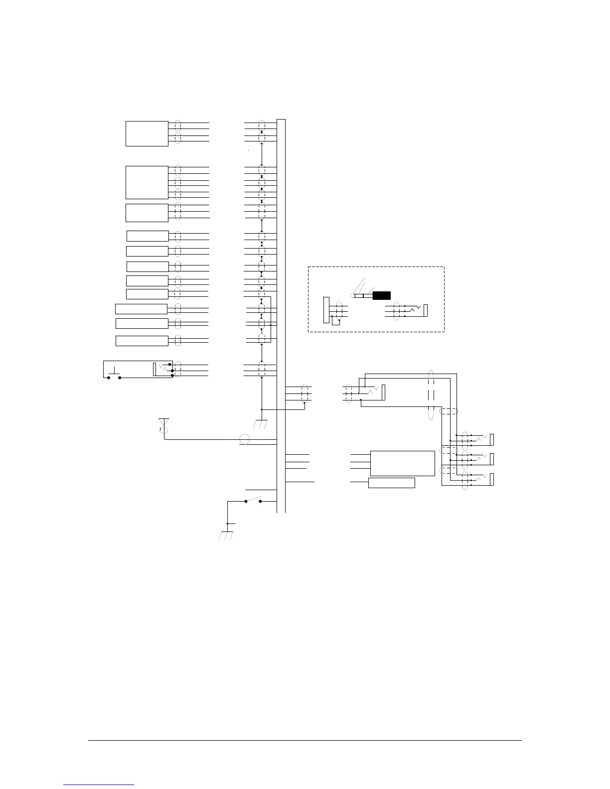
Appendix C – J1 Connector Interconnect
Com 1 Audio Hi
Com 1 Mic Key
Com 1 Lo
Communications
Transceiver #1
Communications
Transceiver #2
Nav 1 Audio Hi
Nav 1 Audio Lo
VHF Nav 1
Nav 2 Audio Hi
Nav 2 Audio Lo
VHF Nav 2
DME Audio Hi
DME Audio Lo
DME Receiver
Com 2 SPR Load
Unswitched Input #1 Hi
Unswitched Audio Lo
Unswitched Audio #1
Unswitched Input #2 Hi
Unswitched Audio Lo
Unswitched Audio #2
Pilot Mic Audio Hi
Pilot Mic PTT
Pilot Mic Lo
36
37
38
39
MKR Ant.
1
2
RG-58A/U Coax
9
10
11
12
Com 1 Mic Audio Hi
Com 2 Audio Hi
Com 2 Mic Key
Com 2 Lo
13
14
15
30
Com 2 Mic Audio Hi
17
18
19
20
21
22
Com 2 Spr Load
Com 2 Spr Load
27
28
31
32
44
43
33
34
35
Telephone
3
4
5
TEL Audio Hi
TEL Mic Audio Hi
TEL Audio Lo
ADF Audio Hi
ADF Audio Lo
ADF Receiver
7
8
Notes:
1. All shields should be grounded at audio panel only.
Other end remains floating.
2. All Power, and Ground wires shall be #22 gage wire
Lighting #22 AWG, other wires minimum #24 AWG
3. All mic and headphone jacks must be isolated from ground.
4. Speaker loads may be required on some older transceivers.
Consult manufacturer's information.
COM 2 Speaker load is the only one provided in the PMA8000.
5. All shielded wires must be MIL 22750 or 27500.
6. Unswitched inputs 1, is always presented to speaker
and crew headphones, regardless of SPR switch or PTT.
7. RESERVED
8. No connection to pins 25, and 26
9. DME audio is passed when AUX button is pressed
10. Unswitched #3 is adjustable
11. Unswitched #2 is selectable over the speaker
12. For flightmate system, see sect. 2.5
13. When J1-16 is grounded, the copilot position will act as a
passenger station.
Pilot PTT
See Note 4
PMA8000G Connector, J1 (Sub-D 44-pin, male on tray)
Unswitched Input #3 Hi
Unswitched Audio Lo
Unswitched Audio #3
29
See Note 6, 10 & 11
Pass. Phones (R)
Pass Phones (L)
Pass. Phones Lo
Pass. 1 PhonesJack
Pass. 4 Phones Jack
Ext. Marker Lamp (Blue)
Ext. Marker Lamp (White)
Ext. Marker Lamp (Amber)
MM Sense to FCS
White Lamp Output
Blue Lamp Output
Amber Lamp Output
MM Sense
Ext. Marker Annunciator
Pass. 3 Phones Jack
Pass. 2 Phones Jack
3/32" Cellular Jack
TEL Mic Input
TEL Audio
TEL Audio Lo
3
5
4
PMA8000G
J1 Connector
Cellular Plug (typical)
Tip= Microphone out
Ring= Speaker audio
Base=Ground
Cellular Phone
Interconnect
See Note 7
AUX Audio Hi
AUX Audio Lo
AUX Receiver
23
41
40
42
16
Copilot/Pass
28
MSG ACK
24
MSG 4 Trigger
See Note 12
See Note 13